
Installation Sheet


Installation Instructions
4
M968699 Rev. 1.6
1
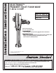
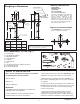
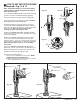
CLOCKWISE CLOSES
CONTROL STOP
COUNTER-CLOCKWISE
OPENS CONTROL STOP
REMOVE COVER
Fig. 6
1. Remove COVER (1) from SUPPLY STOP (2).
2. With a flat blade screwdriver open SUPPLY STOP (2).
3. Turn on water supply to flush line of any debris or
sediment.
4. Close SUPPLY STOP (2) and replace COVER (1).
FLUSH OUT SUPPLY LINES; Fig. 6
4
1
4
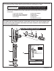
Fig. 7a
Fig. 7c
Fig. 7d
Fig. 7
3
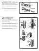
The UNIT is shipped with the inlet flange on the right
side. If needed, the orientation can be reversed by
following the steps below.
1. Loosen SET SCREW (1) with 2.5mm Hex Wrench (4)
in back of top half of FLUSH VALVE (2). Fig. 7a.
2. Rotate TOP (2) to the right and pull off. Fig. 7b.
3. Rotate bottom half of FLUSH VALVE (3) 180˚. Fig. 7b.
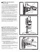
4. Replace TOP (2) and rotate until key engages than
tighten SET SCREW (1). Fig. 7c, 7d.
4 LEFT OR RIGHT HAND
INSTALLATION; Fig. 7
5
4
2
2
Installation Instructions
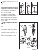
KEY
2
2
1
3
Fig. 7b
180˚
RED+
BLACK-
2