INSTALLATION AND OPERATION MANUAL MODEL 2742 MODEL 2940 MODEL 2748 MODEL 3571 MODEL 2806 MODEL 3572 MODEL 2903 MODEL 3573 MODEL 2932 MODEL 3574 MODEL 2934 MODEL 3575 MODEL 2938 MODEL 3581 BATHTUBS, WHIRLPOOLS, AIR BATHS AND COMBINATION TUBS WITH OPTIONAL CHROMATHERAPY THANK YOU... for selecting an American Standard bath. Your new bath is shipped to you after careful inspection. The whirlpool and air bath versions are completely assembled with pump/blower and system piping.
TABLE OF CONTENTS: Safety Instructions Notice.................................................................Page 3 Installation, Framing and Post Installation Clean-Up Instructions.......................................................................Page 4 Roughing-in References for Recess Type Installations.....................Page 5 Roughing-in References for Pier Type Installations...........................Page 6 Under Deck Mounting Instructions....................................................
IMPORTANT SAFETY INSTRUCTIONS READ AND FOLLOW ALL INSTRUCTIONS! ! WARNING: Risk of personal injury. Do not permit children to use this bathtub without adult supervision. Never drop or insert any object into any opening. Do not operate this unit without the guard over the suction fitting. ! WARNING: Risk of electric shock. Do not permit electrical appliances near any bathtub when bathtub contains water. ! WARNING: Risk of hyperthermia and possible drowning.
Installation and Framing Instructions Each bath arrives ready for installation, completely equipped with the pump/blower electronics and plumbing necessary for operation. However, a drain/overflow kit is required for each bath and it is not included. The variety of installations for this bath may require framing procedures other than those shown. Locate studs as required. Ensure roughing-in dimensions are proper, plumb, and square. ! Remove the bath from the carton.
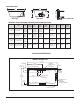
ROUGH-IN REFERENCES FOR RECESS TYPE INSTALLATIONS C D 12" (305 mm) W E NOTE: FRONT EDGE OF BATH MUST BE SUPPORTED BY STUD WALL OR AMERICAN STANDARD APRON KIT LEVELING STRINGERS 24" (610 mm) ACCESS PANEL MUST BE LOCATED ON THE SAME SIDE AS THE MOTOR. ALLOW OPEN FRAMING ON PUMP/MOTOR END FOR SERVICE. ACCESS PANELS NOT REQUIRED FOR BATH TUBS UNLESS AN ACCESS OPENING OF AT LEAST 12" x 24" (305 x 610mm) IS PROVIDED, WARRANTY SERVICE WILL NOT BE PERFORMED.
ROUGH-IN REFERENCES FOR PIER TYPE INSTALLATIONS AS DESIRED F CUTOUT G CUTOUT C 12" (305 mm) AS DESIRED MOUNTING SURFACE WATERPROOF SEALANT BATH 24" (610 mm) ACCESS PANEL MUST BE LOCATED ON THE SAME SIDE AS THE MOTOR. ALLOW OPEN FRAMING ON PUMP/MOTOR END FOR SERVICE. ACCESS PANELS NOT REQUIRED FOR BATH TUBS UNLESS AN ACCESS OPENING OF AT LEAST 12" X 24" (305 X 610mm) IS PROVIDED, WARRANTY SERVICE WILL NOT BE PERFORMED.
SPECIFICATIONS: L W J H C SIDE VIEW A END VIEW DRAIN / OVERFLOW B GENERAL SPECIFICATIONS FOR WHIRLPOOLS AND BATH TUBS Description Dimensions L-W-H 2742 Town Square 6' x 42" L 71-1/2" (1816mm) W 41-3/4" (1060mm) H 22" (559mm) A 16-1/4" (413mm) B 13-1/4" (337mm) C 20" (508mm) 2748 Town Square 5' x 42" L 59-1/2" (1511mm) W 41-5/8" (1057mm) H 23" (584mm) A 14-1/2" (368mm) B 14-1/2" (368mm) Drain / Height to Cut Out Overflow Underside of Pier Deck Edge: C GxF L 72" (1829mm) 2806 Heritage Oval
ROUGH-IN REFERENCES MODEL SERIES 2748 59-1/2" (1511mm) INTEGRAL FITTING DECK 3" X 14" (76 X 356mm) 29-7/8" (759mm) 14-1/2" (368mm) FLOOR CUTOUT 5" X 12" (127 X 305mm) 41-5/8" (1057mm) 3" (76mm) 5-1/4" (133mm) C/L OF DRAIN OUTLET EDGE OF FLOOR CUTOUT 3/4" (19mm) PROVIDE ACCESS TO PUMP SERVING ON ALL INSTALLATIONS OUTLINE OF CUTOUT 58-1/4" X 40-1/4" (1480 X 1022mm) MODEL SERIES 2806 72" (1829mm) 11" (279mm) 18" (457mm) 35-3/4" (908mm) 9" x 13" (229 x 330mm) FLOOR CUTOUT INTEGRAL FITTING DECK
ROUGH-IN REFERENCES MODEL SERIES 2903 60" (1524mm) 9-1/2" (241mm) 42-1/4" (1073mm) OUTLINE OF CUTOUT - USE TEMPLATE 12" (305mm) X 9"(229mm) CUTOUT IN FLOOR FOR DRAIN 21-1/8" (537mm) PROVIDE ACCESS TO PUMP SERVING ON ALL INSTALLATIONS 3" (76mm) CL OF DRAIN OUTLET 9 754532-100 Rev.
SPECIFICATIONS: L W J H SIDE VIEW C A END VIEW B DRAIN / OVERFLOW GENERAL SPECIFICATIONS FOR STUDIO 5' x 32" WHIRLPOOLS AND BATH TUBS Dimensions L-W-H Description Deck Trim Option Drain / Overflow Height to Underside of Deck Edge: C Cut Out Pier GxF Rough-In Recess ExD Tub Edge to Centerline Overflow: J Weight with Water / Floor Loading Product Weight Gallon to Overflow Whirlpool Operating Volume 2932 Studio 5' x 32" Zero (5/8") L 59-1/2" (1511mm) W 31-1/2" (800mm) H 22-1/2" (572mm)
SPECIFICATIONS: L W J H C SIDE VIEW A END VIEW DRAIN / OVERFLOW B GENERAL SPECIFICATIONS FOR STUDIO 5' x 36" WHIRLPOOLS AND BATH TUBS Dimensions L-W-H Description Deck Trim Option Drain / Overflow Height to Underside of Deck Edge: C Cut Out Pier GxF Rough-In Recess ExD 2934 Studio 5' x 36" Zero (5/8") L 59-1/2" (1511mm) W 35-1/2" (902mm) H 22-1/2" (572mm) A 17-3/4" (451mm) B 10-3/4" (273mm) C 21-7/8" (556mm) 58" (1473mm) x 34" (864mm) 59-11/16" (1516mm) x 34" (864mm) 2934 Studio 5' x
SPECIFICATIONS: L W J H SIDE VIEW C A END VIEW DRAIN / OVERFLOW B GENERAL SPECIFICATIONS FOR STUDIO 5-1/2' x 36" WHIRLPOOLS AND BATH TUBS Dimensions L-W-H Description Deck Trim Option Drain / Overflow Height to Underside of Deck Edge: C Cut Out Pier GxF Rough-In Recess ExD 2938 Studio 5-1/2' x 36" Zero (5/8") L 65-1/2" (1664mm) W 35-1/2" (902mm) H 22-1/2" (572mm) A 17-3/4" (451mm) B 10-3/4" (273mm) C 21-7/8" (556mm) 64" (1626mm) x 34" (864mm) 65-11/16" (1668mm) x 34" (864mm) 2938 Stu
SPECIFICATIONS: L W J H SIDE VIEW C A END VIEW DRAIN / OVERFLOW B GENERAL SPECIFICATIONS FOR STUDIO 6' x 36" WHIRLPOOLS AND BATH TUBS Dimensions L-W-H Description Deck Trim Option Drain / Overflow Height to Underside of Deck Edge: C Cut Out Pier GxF Rough-In Recess ExD 2940 Studio 6' x 36" Zero (5/8") L 71-1/2" (1816mm) W 35-1/2" (902mm) H 22-1/2" (572mm) A 17-3/4" (451mm) B 10-3/4" (273mm) C 21-7/8" (556mm) 70" (1778mm) x 34" (864mm) 71-11/16" (1821mm) x 34" (864mm) 2940 Studio 6' x
SPECIFICATIONS: L W J H SIDE VIEW C A END VIEW B DRAIN / OVERFLOW GENERAL SPECIFICATIONS FOR GREEN TEA WHIRLPOOLS AND BATH TUBS Description Dimensions L-W-H 3571 Green Tea 5' x 36" L 60" (1524mm) W 36" (914mm) H 21" (533mm) A 16" (406mm) B 11-1/2" (349mm) 3572 Green Tea 5-1/2' x 36" L 66" (1676mm) W 36" (914mm) H 21" (533mm) 3573 Green Tea 6' x 36" Drain / Overflow Height to Underside of Deck Edge: C Cut Out Pier GxF Rough-In Recess ExD Tub Edge to Centerline Overflow: J Weight with W
ROUGH-IN REFERENCES MODEL SERIES 3572 66" (1676mm) 14-3/4" (375mm) 11-1/2" (292mm) 36" (914mm) 9" (229mm) C L CUTOUT IN FLOOR FOR DRAIN PROVIDE ACCESS TO PUMP SERVING ON ALL INSTALLATIONS OUTLINE OF CUTOUT 64.5" x 34.5" (1638 x 876mm) MODEL SERIES 3573 72" (1829mm) 14-3/4" (375mm) 11-1/2" (292mm) 36" (914mm) 9" (229mm) CL CUTOUT IN FLOOR FOR DRAIN PROVIDE ACCESS TO PUMP SERVING ON ALL INSTALLATIONS OUTLINE OF CUTOUT 70.5" x 34.5" (1780 x 876mm) 15 754532-100 Rev.
ROUGH-IN REFERENCES MODEL SERIES 3574 60" (1524mm) 14-3/4" (375mm) 11-1/2" (292mm) 42" (1067mm) 9" (229mm) CL CUTOUT IN FLOOR FOR DRAIN PROVIDE ACCESS TO PUMP SERVING ON ALL INSTALLATIONS OUTLINE OF CUTOUT 58.5" x 40.5" (1486 x 1029mm) MODEL SERIES 3575 72" (1829mm) 14-3/4" (375mm) 11-1/2" (292mm) 42" (1067mm) 9" (229mm) CL CUTOUT IN FLOOR FOR DRAIN PROVIDE ACCESS TO PUMP SERVING ON ALL INSTALLATIONS OUTLINE OF CUTOUT 70.5" x 40.5" (1780 x 1029mm) 16 754532-100 Rev.
SPECIFICATIONS: L W J H SIDE VIEW C A END VIEW B DRAIN / OVERFLOW GENERAL SPECIFICATIONS FOR SERIN WHIRLPOOLS AND BATH TUBS Description Dimensions L-W-H Drain / Overflow Height to Underside of Deck Edge: C Cut Out Pier GxF Rough-In Recess ExD Tub Edge to Centerline Overflow: J Weight with Water / Floor Loading Product Weight Gallon to Overflow 3581 Serin 5' x 32" L 60" (1524mm) W 32" (813mm) H 23" (584mm) A 16-3/4" (425mm) B 10-1/4" (260mm) C 20" (508mm) 58-1/2" (1486mm) x 30-1/2" (7
ELECTRICAL INSTALLATION INSTRUCTIONS All wiring must be performed by a licensed electrician in accordance with the national electrical code and all other applicable codes. ! WARNING: When using electrical products, basic precautions should always be observed, including the following: 1. DANGER: RISK OF ELECTRIC SHOCK! Connect only to a circuit protected by a ground-fault circuit interrupter. 2. Grounding is required. The unit should be installed by a licensed electrician and grounded. 3.
ELECTRICAL INSTALLATION INSTRUCTIONS (continued) ELECTRICAL FEED 120V, 60HZ 15A GFCI GFCI ELECTRONIC ACTIVATED AIR BATH (4 BUTTON PANEL) ELECTRICAL FEED 120V, 60HZ 15A GFCI GFCI ELECTRONIC ACTIVATED AIR BATH WITH LIGHTS (5 BUTTON PANEL) 19 754532-100 Rev.
ELECTRICAL INSTALLATION INSTRUCTIONS (continued) ECOSILENT PUMP HAS P3JJ PLUG ELECTRICAL FEED 120V, 60HZ 15A GFCI GFCI ELECTRONIC ACTIVATED ECOSILENT WHIRLPOOL (1 BUTTON PANEL) ECOSILENT PUMP HAS P3JJ PLUG ELECTRICAL FEED 120V, 60HZ 15A GFCI GFCI ELECTRONIC ACTIVATED ECOSILENT WHIRLPOOL WITH LIGHTS (3 BUTTON PANEL) 20 754532-100 Rev.
ELECTRICAL INSTALLATION INSTRUCTIONS (continued) USE THREE GFCI OUTLETS (USA MARKET) ELECTRICAL FEED 120V, 60HZ 15A GFCI (FOR HEATER) WHIRLPOOL HEATER IS FACTORY INSTALLED ON COMBINATION TUBS GFCI ECOSILENT PUMP HAS P3JJ PLUG ELECTRICAL FEED 120V, 60HZ 15A GFCI GFCI ELECTRICAL FEED 120V, 60HZ 15A GFCI GFCI ELECTRONIC ACTIVATED COMBINATION TUB WITH LIGHTS (4 BUTTON PANEL) 21 754532-100 Rev.
ELECTRICAL INSTALLATION INSTRUCTIONS (continued) USE THREE JUNCTION BOXES (CANADA MARKET) ELECTRICAL FEED 120V, 60HZ 15A GFCI (FOR HEATER) GFCI White Black Green/Copper ELECTRICAL FEED 120V, 60HZ 15A GFCI GFCI ECOSILENT PUMP HAS P3JJ PLUG White Black Green/Copper ELECTRICAL FEED WHIRLPOOL HEATER IS FACTORY INSTALLED ON COMBINATION TUBS TO BOX 120V, 60HZ 15A GFCI GFCI TO BOX White Black Green/Copper ELECTRONIC ACTIVATED COMBINATION TUB WITH LIGHTS (4 BUTTON PANEL) 22 754532-100 Rev.
ELECTRICAL INSTALLATION INSTRUCTIONS (continued) (HEATER) Ensure the heater and pump are properly GROUNDED and BONDED as required. Attach the 8 AWG solid copper conductor supplied with the heater from the heater bonding lug to the motor frame bonding lug as shown in Figure 3. HEATER ON The conductor is secured to the lugs using set screws.
REMOTE BLOWER LOCATION OPTION IMPORTANT! It is not necessary that the blower motor be relocated. This option is provided for the case that a particular installation makes this effort practical. NOTE: Relocating blower motor from factory installed location, see photo 1, will require disassembly of air blower from mounting board. Keep all hardware for reattachment at new location. Additional hardware will be required depending upon final desired position of air blower. Follow all instructions listed below.
REMOTE BLOWER LOCATION OPTION (continued) FOR THE COMBINATION WHIRLPOOL / AIR BATH CONFIGURATIONS ONLY: Up to two additional control box extensions (P/N 754512-0070A) are required as shown in photo 4 (below). Simply extend the cables going to the blower by adding in the extension cables. Be careful not to damage the cable connections and never plug in cables while power is applied to blower and/or pump. PUMP LONGER CONTROL PANEL CABLE (754025-0073A) CONTROL PANEL 4.
Operation: Single Speed Whirlpool AIR SWITCH ELECTRONIC SWITCH BATHING: • Fill bath with water at a comfortable bathing temperature - If your whirlpool is equipped with the optional EZ-Heater, it will automatically maintain the water temperature. • IMPORTANT: Do NOT fill the whirlpool more than 2/3 full before getting in, as it may overflow. • IMPORTANT: Do NOT add bath oils or salts – this will damage the whirlpool pump.
Operation: EcoSilent Whirlpool with Lights DISPLAY COLORS 1ST WHITE 2ND SLOW RAINBOW CYCLE 3TH FAST RAINBOW CYCLE 4TH TURQUOISE 5 BLUE TH 3-BUTTON ELECTRONIC SWITCH 6TH MAGENTA 7TH RED TH 8 ORANGE 9TH YELLOW 10 TH GREEN 11 TH RETURN TO SLOW RAINBOW CYCLE BATHING: • Fill bath with water at a comfortable bathing temperature - If your whirlpool is equipped with the optional EZ-Heater, it will automatically maintain the water temperature.
Operation: Air Bath BATHING: • IMPORTANT: DO NOT ADD BATH OILS OR SALTS as they will damage the whirlpool pump and may harm the acrylic surface. • Close drain by rotating Drain Overflow Knob COUNTER-CLOCKWISE • Fill bath with water at a comfortable bathing temperature. OPERATING AIR MASSAGE SYSTEM: ON/OFF: Press this button once to turn air-blower on. Press again to turn air-blower off. AIR SPEED INCREASE: Pressing this button will increase to the next higher speed.
Operation: Air Bath with Lights BATHING: • IMPORTANT: DO NOT ADD BATH OILS OR SALTS as they will damage the whirlpool pump and may harm the acrylic surface. • Close drain by rotating Drain Overflow Knob COUNTER-CLOCKWISE • Fill bath with water at a comfortable bathing temperature. OPERATING AIR MASSAGE and CHROMATHERAPY SYSTEM: ON/OFF: Press this button once to turn air-blower on. Press again to turn air-blower off. AIR SPEED INCREASE: Pressing this button will increase to the next higher speed.
Operation: Air Bath with Lights (continued) EXITING THE BATH • Be sure to turn off the air blower before draining bath. • Open drain by rotating drain knob clockwise. DRYING CYCLE OPTIONS STANDARD DRYING CYCLE An automatic drying cycle will start 20 minutes after the blower is turned off. The blower LED blinks while waiting for the purge cycle. 24H PROGRAMMABLE DRYING CYCLE The system must be stopped prior to activation or deactivation. Activation: Determine at which time you wish to purge to activate.
Operation: Combination Tub with Lights BATHING: • IMPORTANT: DO NOT ADD BATH OILS OR SALTS as they will damage the whirlpool pump and may harm the acrylic surface. • Close drain by rotating Drain Overflow Knob COUNTER-CLOCKWISE • Fill bath with water at a comfortable bathing temperature OPERATING AIR MASSAGE and CHROMATHERAPY SYSTEM: • Press this button to turn blower on. • Press this button again to turn blower off. • Press and hold button to increase blower speed. Release button at desired speed.
Operation: Combination Tub with Lights (continued) EXITING THE BATH • Be sure to turn off the air blower before draining bath. • Open drain by rotating drain knob clockwise. DRYING CYCLE OPTIONS STANDARD DRYING CYCLE An automatic drying cycle will start 20 minutes after the blower is turned off. The blower LED blinks while waiting for the purge cycle. 24H PROGRAMMABLE DRYING CYCLE The system must be stopped prior to activation or deactivation.
Your American Standard whirlpool is designed to give you many years of pleasure with reasonable care and maintenance. Your new acrylic bathtub is tough, durable and easy to care for. The colors have been formulated to match other American Standard fixtures and enhance your choice of bathroom decorations. The high gloss surface will retain its lasting luster with proper care and maintenance. CLEANING AND MAINTENANCE: • Always fill the tub with temperate water.
AS America, Inc. Limited Lifetime Warranty for Premium Acrylic Air Baths AS America, Inc. (”American Standard”) warrants to the original consumer purchaser that it will, at its option, repair or replace this whirlpool or any of its parts that are found by American Standard, in its sole judgment, to be defective under normal residential use and maintenance so long as it is owned by the original consumer purchaser.