
Installation Guide


2
M965802 Rev.1.2 (11/18)
3
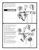
CONNECT SPRAY HOSE AND SOLENOID ASSEMBLY,
AND INSTALL WEIGHT
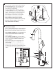
• Turn off hot and cold water supplies before beginning.
• Install INLINE FILTER (3) on each wall supply outlet.
Be sure that INLINE FILTER (3) is inserted in the
correct direction. (See Illustration)
• Connect FLEXIBLE SUPPLY HOSES (1, 2) directly
to INLINE FILTER (3). Connection on tting supplies
are 3/8" compression. Connect left supply hose (Red
Stripe) to Hot wall supply. Connect right supply hose
(Blue Stripe) to Cold wall supply. Use adjustable
wrench to tighten connections. Do not over tighten.
*
Faucet supplies are 35" long from faucet base.
• Note: If additional supply length is required,
installer must purchase additional parts separately.
• Important: If SUPPLY HOSES (1, 2) are too long,
loop as illustrated to avoid kinking.
MAKE WATER SUPPLY CONNECTIONS
8
7
9
3
2
4
1
18"
6
5
A
B
- 2 -
• Push the SPRAY HOSE END (1) into FEMALE ADAPTER
(2) and slide down locking collar to secure connection.
• Orient solenoid valve with the orientation label facing up.
• Push SOLENOID ASSEMBLY (3) connection “B” into the
HOSE CONNECTOR (4) as shown, and slide down
locking collar towards SOLENOID ASSEMBLY (3) to
secure connection.
• Push SOLENOID ASSEMBLY (3) connection “A” into
other end of FEMALE ADAPTER (2) as shown, and slide
locking collar towards SOLENOID ASSEMBLY (3) to
secure connection.
• With HAND SPRAY (5) seated in SPOUT (6), install
WEIGHT (7) at labeled area onto HOSE (8), secure
with SCREW (9).
• Important: Make sure you pull out hose and check to
see that it moves freely and is not obstructed by supply
hoses, solenoid valve or items in the bottom of the
cabinet.
Slide
locking
collar to
secure
UP
Locking
Collar
IMPORTANT: Do not
use sealent on threads
1
2
3
COLD
HOT
(3) INLINE
FILTER