
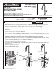
Specification


5
ELECTRICAL CONNECTIONS – BATTERY HOLDER
ELECTRICAL CONNECTIONS - SENSOR TO SOLENOID
4
M965686 Rev. 1.2 (4/16)
5
9
6
7
1
12
3
11
2
UP
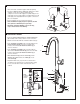
• Connect SOLENOID CONNECTOR (12) with
the sensor connector from the faucet with the
yellow tag stickers, secure this connection by
installing inside the CONNECTORS HOUSING
(3) as shown and lock by twisting the white
end pieces.
NOTE:
Use Qty. (4) AA Alkaline type
batteries only.
- 3 -
• Identify desired battery holder location. Battery
holder should be located so batteries can be
easily accessed, with in 6ft of the faucet hook
and loop (black strip).
• Attach CABLE MOUNTS (4) along the inside
of the kitchen cabinet walls positioning them
accordingly as shown. Wipe clean surfaces
before attaching CABLE MOUNTS (4).
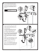
• Attach ‘HOOK TO LOOP’ FASTENER (black strip)
(5) to the back side of the BATTERY HOLDER (7)
and attach ‘HOOK TO LOOP’ FASTENER (black
strip) (5) on desired location inside the kitchen
cabinet. Wipe mounting surface clean before
attaching ‘HOOK TO LOOP’ FASTENER (black
strip) (5).
• Secure longer SENSOR CABLE (6) to the CABLE
MOUNTS (4) using the WIRE TIES (8) provided.
• Ensure that the BYPASS KNOB (10) on the
SOLENOID ASSEMBLY (1) is in the “OFF”
position.
• With the SLIDING DOOR (11) in the open
position, connect the BATTERY HOLDER CABLE
(9) to the other end of the long SENSOR CABLE
(6), that is coming out of the faucet. The sensor
will start to blink several times and then stop.
5
9
6
7
1
12
10
8
4
2
UP
11