
Installation Sheet


3
CAUTION: Use only American Standard supplied
transformers and cable sets. Using non-AS supplied
cables, or cutting, splicing or modifying any components
will void the warranty.
M965647 REV. 1.4 (7/15)
1. Installation Instructions
2. Flush Valve Body Assembly
3. Vacuum Breaker Tube
4. Spud Coupling Nut and Washers
5. Spud Flange
6. Wall Escutcheon
7. Cover Tube
8. Sweat Adapter
9. Stop Valve
GENERAL DESCRIPTION:
SELECTRONIC™ PROXIMITY URINAL FLUSH VALVE
Exposed Flushometer for 3/4" Top Spud Fixtures
Exclusive, self cleaning piston-type ush valve with
proximity operation and manual override. Operates
on DC (battery) power. Recommended operating
pressure 35 to 80 psi. Can install left or right-handed.
Detection Zone can also be adjusted manually, or
with optional remote control.
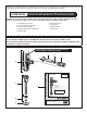
412 mm
(16-1/2")
292 mm
(11-1/2")
120 mm
(4-3/4")
73 mm
(2-7/8")
(1" NPT)
15˚
305 mm MÁX.
(12" MÁX.)
76mm MAX.
(3) MAX.
L-C-
*Note: The Critical Line (-C-L-) on Vacuum
Breaker must typically be 6
" (152mm) above
fixture. Consult Codes for details.
FINISHED WALL
108mm-134mm
(4-1/4" TO 5-1/4")
FOR 3/4" TOP
SPUD FIXTURES
MANUAL
OVERRIDE
BUTTON
DETECTION ZONE
400mm-800mm
(15-3/4 TO 31-1/2)
*-C-L-
152mm MIN.
(6") MIN.
Fig. 2
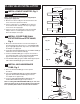
1
2
3
4
5
6
7 9 10
8
10'
Roughing-in Dimensions Fig. 1
Right or Left Hand Installation
See (Section 5) for converting Flush
Valve to Left Hand Installation.
RECOMMENDED TOOLS; Fig. 2.
1. Teon Tape
2. Flat Blade Screwdriver
3. Adjustable Wrench
4. Tape Measure
5. Hacksaw
6. Tubing Cutter
7. File
8. For Sweat Connection; Solder and Torch
9. 2.5mm Hex Wrench
10. 1.5mm Hex Wrench
PRIOR TO INSTALLATION
Note: Prior to installing the Selectronic™Flush
Valve the following items must be installed.
1. Urinal
2. Drain line
3. Water supply line
IMPORTANT:
• All plumbing and electrical wiring should be
installed in accordance with applicable codes
and regulations.
• The use of water hammer arrestors is strongly
recommended for commercial applications. All piping
behind the walls should be properly secured and
fastened.
• Water supply lines must be sized to provide an
adequate volume of water for each xture.
• Flush all water lines prior to operation (See Step 4).
Dirt and debris can cause ush valve to run continuously.
• With the exception of Stop Valve Inlet, DO NOT
use pipe sealant or plumbing grease on any
valve component or coupling!
• Protect the chrome or special nish on the Flushometer.
DO NOT USE toothed tools on nished surfaces to install
or service these valves. Also see “Care and Cleaning”
section of this manual.
• This product contains mechanical and/or electrical
components that are subject to normal wear. These
components should be checked on a regular basis and
replaced as needed to maintain the valve’s performance.