
Installation Sheet


5
M965022 Rev. 2.2 (5/19)
4
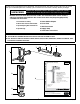
INSTALL FLUSH VALVE; Fig. 6a & 6b
1. As shown in Fig. 6a, insert the side INLET FLANGE (1)
on the FLUSH VALVE (2) into the SUPPLY STOP (3).
Lubricate the INLET FLANGE O-RING (4) with water if
necessary. Lightly tighten COUPLING NUT (5). Fig. 6a.
Important: Do not use lubricants (other than water) or
any type of thread sealing paste or tape.
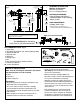
2. Align the FLUSH VALVE (2) (Fig. 6b) directly above the
DOWN TUBE (7) and VACUUM BREAKER COUPLING
NUT (6).
Note: There is a ±13mm, (±1/2) tolerance for the 121mm
(4-3/4) dimension. Fig. 6b.
3. Pull the DOWN TUBE (7) up to meet the threaded FLUSH
VALVE CONNECTION (8) and hand tighten the VACUUM
BREAKER COUPLING NUT (6). Align all components of
the ush valve assembly. Fig. 6b.
4. Lightly tighten the COUPLING NUT (5) connection rst,
then the VACUUM BREAKER COUPLING NUT (6) and
nally the SPUD COUPLING NUT (9). Once alligned
correctly, use a wrench to tighten couplings to make water
tight connections. Fig. 6b.
5
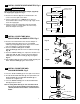
FLUSH OUT SUPPLY LINES; Fig. 7
1. Remove COVER (1) from SUPPLY STOP (2). Make sure
supply stop is closed.
2. Remove FLUSH VALVE CAP (3). Pull out PISTON (4).
Replace FLUSH VALVE CAP (3) and tighten.
3. With a at blade screwdriver open SUPPLY STOP (2).
to ush line of any debris or sediment.
4. Close SUPPLY STOP (2). Remove FLUSH VALVE
CAP (3). Replace PISTON (4). Replace FLUSH
VALVE CAP (3) and tighten.
3
2
5
1
4
Fig. 6a
7
9
6
2
5
8
121mm, 13mm
(4-3/4)( 1/2)
Fig. 6b
+
–
+
–
Fig. 7
REMOVE COVER
2
1
CLOCKWISE
CLOSES CONTROL STOP
COUNTER-CLOCKWISE
OPENS CONTROL STOP
3
4