Installation Instructions Ultima™ Manual MODEL NUMBERS Toilet Flush Valve, Piston-Type 1-1/2" Top Spud 6047 Series 7017 Series OPERATING PRESSURE: • 25 psi (flowing) - 80 psi (static) FLOW REQUIREMENT: • 25gpm (94.6 L/min). Certified to comply with: • ASSE 1037 • ANSI/ASME A112.19.2 • ADA Compliant NOTE TO INSTALLER: Please give this manual to the customer after installation. To learn more about American Standard Selectronic® Products visit our website at: www.americanstandard-us.
Thank you for selecting American-Standard...the benchmark of fine quality for over 100 years. To ensure that your installation proceeds smoothly--please read these instructions carefully before you begin. UNPACKING All American Standard Products Are Water Tested At Our Factory. Some Residual Water May Remain In The Valve During Shipping emove the Flush Valve items from the carton. The illustration below shows all items R after they have been removed from the carton.
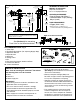
Roughing-in Dimensions GENERAL DESCRIPTION FINISHED WALL Fig.1 MANUAL FLUSH VALVE Exposed Flushometer for 1-1/2" Top Spud Fixtures 38mm-127mm (1-1/2-5") SUPPLY DN 25 mm (1" I.P.S.) 6047.122 ROUGH-IN DIMENSION 686 mm (27") 108-133 mm (4-1/4" to 5-1/4") 6047.117 660 mm (26") 6047.121 ROUGH-IN DIMENSION 292 mm (11-1/2") -C-L- *CRITICAL LEVEL 6047.122 735 mm (29") 6047.117 ROUGH-IN DIMENSION 610 mm (24") 152 mm (6 " ) (Min.) 6047.
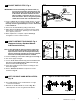
1 INSTALL SWEAT SOLDER ADAPTER; Fig. 3 CAUTION Fig.3 Fig.3a FINISHED WALL Turn off hot and cold water supplies before beginning. A Note: Install Optional Sweat Solder Adapter (Supplied) for copper pipe supply line. Fig. 3. (A-B)= C 1. Measure the distance (A) from the finished wall to the center of the inlet spud on the fixture. 2. C ut the supply pipe 1-1/4" (A-B=C) shorter then the measurement taken in Step 1. File any rough edges off the end of the supply pipe. 3.
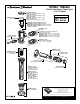
4 INSTALL FLUSH VALVE; Fig. 6a & 6b Fig. 6a 3 1. As shown in Fig. 6a, insert the side INLET FLANGE (1) on the FLUSH VALVE (2) into the SUPPLY STOP (3). Lubricate the INLET FLANGE O-RING (4) with water if necessary. Lightly tighten COUPLING NUT (5). Fig. 6a. Important: Do not use lubricants (other than water) or any type of thread sealing paste or tape. 2. Align the FLUSH VALVE (2) (Fig. 6b) directly above the DOWN TUBE (7) and VACUUM BREAKER COUPLING NUT (6).
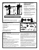
ADJUST SUPPLY STOP; Fig. 8 Fig. 8 REMOVE COVER IMPORTANT: To avoid overflowing, the SUPPLY STOP (3) must never be opened to the point where the flow from the valve exceeds the flow capacity of the fixture. The fixture and drain must be able to handle a continuous flow in case of a flush valve failure. Valve is designed to provide stated flush volume with a 25 GPM flow rate. 3 CLOCKWISE CLOSES CONTROL STOP 1. R emove COVER (2) from SUPPLY STOP (3).
Ultima™ Manual M962921-0070A CAP SEAL M970211-0021100A (MANUAL FLUSH VALVE CAP, 1.1 gpf) M970211-0021280A (MANUAL FLUSH VALVE CAP, 1.28 gpf) M970211-002160A (MANUAL FLUSH VALVE CAP, 1.6 gpf) M970211-0026500A (MANUAL FLUSH VALVE CAP, 6.5 gpf) Toilet Flush Valve, Piston-Type 1-1/2" To Spud MODEL NUMBERS 6047 Series 7017 Series M964905K-0071100A (MODEL 6047.111) M964905A-0071600A (MODEL 6047.161) M964905B-0071280A (MODEL 6047.121, 7017.121) M964905H-0076500A (MODEL 6047.117, 6047.
Consignes d’installation Ultima,MC manuel NUMÉROS DE MODÈLE Robinet de chasse de toilette, à piston ligature de 1-1/2 po sur le dessus Série 6047 Série 7017 PRESSION DE FONCTIONNEMENT : • 25 lb/po2 (écoulement) - 80 lb/po2 (statique) EXIGENCE RELATIVE AU DÉBIT : • 25 gpc (94,6 L/min). Homologué conforme à : • ASSE 1037 • ANSI/ASME A112.19.2 • ADA REMARQUE À L’INTENTION DE LA PERSONNE RESPONSABLE DE L’INSTALLATION : une fois l’installation terminée, veuillez remettre cette notice au client.
Nous vous remercions d’avoir choisi American Standard… la référence en matière de qualité depuis plus de 100 ans. Pour une installation sans problème, veuillez lire attentivement ces consignes avant de commencer. DÉBALLAGE Tous les produits d’American Standard sont mis à l’essai en usine. Il peut donc rester de l’eau dans le robinet durant le transport. Retirer les éléments du robinet de chasse d’eau de l’emballage.
Dimensions de la robinetterie brute Fig.1 DESCRIPTION GÉNÉRALE : MUR FINI ROBINET DE CHASSE D’EAU MANUELLE Compteur de chasses d’eau pour installations fixes à ergot supérieur de 1 ½ po 38 mm-127 mm (1 ½ -5 po) 6047.122 DIMENSIONS DE LA ROBINETTERIE BRUTE 686 mm (27 po) ALIMENTATION 108 mm-133 mm DN 25 mm (4 ¼ po à 5 ¼ po) (1po IPS) -C-L- *NIVEAU CRITIQUE 152 mm (6 po ) (Min.) 6047.
DE L’ADAPTATEUR 1 INSTALLATION DE CORPS DE SOUDURE ; Fig. 3 ATTENTION Fig.3 Fig.3a LIGNE CENTRALE DE L’ERGOT DE L’INSTALLATION FIXE MUR FINI Couper l’alimentation d’eau chaude et d’eau froide avant de commencer. A Remarque : installer l’adaptateur de corps de soudure optionnel (compris) pour la conduite d’alimentation du tuyau en cuivre. Fig. (A-B)= C B 32mm (1 ¼ po) LIMER LES REBORDS RUGUEUX 1.
4 INSTALLATION DU ROBINET DE Fig. 6a 3 CHASSE D’EAU ; Fig. 6a et 6b 1. Tel qu’illustré à la Fig. 6a, insérer la BRIDE D’ENTRÉE (1) latérale se trouvant sur le ROBINET DE CHASSE D’EAU dans la BUTÉE D’ALIMENTATION (3). Lubrifier le JOINT TORIQUE DE BRIDE D’ENTRÉE (4) avec de l’eau si nécessaire. Serrer légèrement l’ÉCROU D’ACCOUPLEMENT (5). Fig. 6a. Important : Ne pas utiliser de lubrifiants (autre que de l’eau) ou tout type de pâte à sceller pour le filetage. 1 2 2.
DE LA BUTÉE 6 AJUSTEMENT Fig. 8 RETIRER LE COUVERCLE D’ALIMENTATION ; Fig. 8 IMPORTANT : P our éviter tout débordement, la BUTÉE D’ALIMENTATION (3) ne doit jamais être ouverte au point où le débit du robinet dépasse la capacité de débit de l’installation fixe. L’installation fixe et le renvoi doivent être en mesure d’accepter un débit continu en cas de défaillance du robinet de chasse d’eau. Le robinet est conçu pour fournir un débit de chasse d’eau de 25 GPC.
Ultima,MC manuel Robinet de chasse de toilette, à piston ligature de 1-1/2 po sur le dessus M962921-0070A JOINT D’ÉTANCHÉITÉ DU CAPUCHON M970211-0021100A (RINCER LE BOUCHON DU ROBINET MANUEL, 1.1 gpf) M970211-0021280A (RINCER LE BOUCHON DU ROBINET MANUEL, 1.28 gpf) M970211-002160A (RINCER LE BOUCHON DU ROBINET MANUEL, 1.6 gpf) M970211-0026500A (RINCER LE BOUCHON DU ROBINET MANUEL, 6.5 gpf) NUMÉROS DE MODÈLE Série 6047 Série 7017 M964905K-0071100A (MODÈLE 6047.111) M964905A-0071600A (MODÈLE 6047.
Instrucciones de Instalación Ultima™ Manual NÚMEROS DE MODELO Válvula de descarga del inodoro, pistón spud superior de 1-1/2” Serie 6047 Serie 7017 PRESIÓN DE OPERACIÓN: • 25 psi (en flujo) - 80 psi (estático) REQUERIMIENTO DE FLUJO: • 25gpm (94.6 L/min). Certificado para cumplir con las normas: • ASSE 1037 • ANSI/ASME A112.19.2 • ADA Compliant NOTA PARA EL INSTALADOR: Entregue este manual al cliente después de la instalación.
Gracias por elegir American Standard...el referente de fina calidad por más de 100 años. Para asegurarse que su instalación proceda correctamente, por favor lea estas instrucciones antes de comenzar. DESEMBALAJE Todos Los Productos De American Standard Son Probados Con Agua En La Fábrica. Puede Haber Agua En La Llave Al Recibirla. Remueva del cartón los componentes de la Válvula de Descarga. La ilustración de abajo muestra todos los componentes una vez removidos de la caja.
Dimensiones de Instalación DESCRIPCIÓN GENERAL Fig.1 VÁLVULA DE DESCARGA MANUAL Fluxómetro Expuesto para Ensambles de Entrada Superior de 1-1/2" 38 mm-127 mm (1-1/2-5") PRESIÓN DE OPERACIÓN: ALIMENTACIÓN DN 25 mm (1" I.P.S.) 6047.122 ROUGH-IN DIMENSION 686 mm (27") 108 mm-133 mm (4-1/4" a 5-1/4") -C-L- 6047.117 660 mm (26") 6047.121 ROUGH-IN DIMENSION 292 mm (11-1/2") 6047.117 ROUGH-IN DIMENSION 610 mm (24") *NIVEL CRÍTICO 152 mm (6 " ) (Min.) 6047.122 735 mm (29") 6047.
EL ADAPTADOR DE SOLDADURA; 1 INSTALE Fig. 3 PRECAUCIÓN Fig.3 Fig.3a MURO ACABADO Cierre los suministros de agua caliente y fría antes de comenzar. A Nota: Instale el Adaptador de Soldadura Opcional (Incluido) para la línea de alimentación de cobre. Fig. 3. (A-B)= C 1. Mida la distancia (A) desde el muro acabado hasta el centro de la entrada del ensamble. 2. Corte la línea de alimentación 1-1/4" (A-B=C) mas corta que la medida tomada en el Paso 1. Lije cualquier extremo rugoso de la tubería. 3.
4 INSTALE LA VÁLVULA DE FLUJO; Fig. 6a 3 Fig. 6a & 6b 1. Como se muestra en la Fig. 6a, inserte la BASE DE ENTRADA (1) en la VÁLVULA DE DESCARGA (2) en el BORDE DE ALIMENTACIÓN (3). Lubrique la ARANDELA DE GOMA DE LA ENTRADA (4) con aga. Apriete la TUERCA DE ASOCIACIÓN (5). Fig. 6a. Importante: No use lubricantes (mas que el agua) o ningun tipo de sellador de roscas. 2. A linee la VÁLVULA (2) (Fig. 8b) directamente sobre el TUBO DE BAJADA (7) y la TUERCA DE ASOCIACIÓN DEL IGUALADOR (6).
EL BORDE DE ALIMENTACIÓN; 6 AJUSTE Fig. 8 Fig. 8 REMUEVA LA CUBIERTA IMPORTANTE: Para evitar que se desborde, el BORDE DE ALIMENTACIÓN (3) nunca se debe abrir al punto donde el flujo de la válvula excede la capacidad del ensamble. El ensamble debe poder con el flujo contínuo en caso de una falla en la válvula. La válvula está diseñada ára un volumen de descarga de 10 GPM. 3 2 EN CONTRA DE LAS MANECILLAS ABRE EL BORDE DE CONTROL 1. R emueva la CUBIERTA (2) del BORDE DE ALIMENTACIÓN (3).
Ultima™ Manual Válvula de descarga del inodoro, pistón spud superior de 1-1/2” M962921-0070A SELLO DE TAPA NÚMEROS DE MODELO M970211-0021100A (TAPA DE VÁLVULA DE DESCARGA MANUAL, 1.1 gpf) M970211-0021280A (TAPA DE VÁLVULA DE DESCARGA MANUAL, 1.28 gpf) M970211-002160A (TAPA DE VÁLVULA DE DESCARGA MANUAL, 1.6 gpf) M970211-0026500A (TAPA DE VÁLVULA DE DESCARGA MANUAL, 6.5 gpf) Serie 6047 Serie 7017 M964905K-0071100A (MODELO 6047.111) M964905A-0071600A (MODELO 6047.161) M964905B-0071280A (MODELO 6047.