
Installation Guide

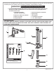


M965403 REV. 1.1
10
6
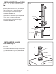
Fig. 10
1. Remove COVER (1) from SUPPLY STOP (2). Make
sure supply stop is closed.
2. Remove FLUSH VALVE CAP (3). Pull out PISTON (4).
Replace FLUSH VALVE CAP (3) and tighten.
3. With a flat blade screwdriver open SUPPLY STOP (2).
to flush line of any debris or sediment.
4. Close SUPPLY STOP (2). Remove FLUSH VALVE
CAP (3). Replace PISTON (4). Replace FLUSH VALVE
CAP (3) and tighten.
FLUSH OUT SUPPLY LINES; Fig. 10
8
REMOVE COVER
2
1
CLOCKWISE
CLOSES CONTROL STOP
COUNTER-CLOCKWISE
OPENS CONTROL STOP
3
4
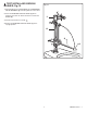
Fig. 12
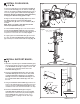
IMPORTANT: To avoi d ove rflow in g, the SU PP LY STOP
(3) must never be opened to the point where the flow
from the valve exceeds the flow capacity of the
fixture. The fixture and drain must be able to handle a
continuous flow in case of a flush valve failure.
Valve is designed to provide stated flush volume with
a 25 GPM flow rate.
1. Remove COVER (2) from SUPPLY STOP (3).Turn on
water supply 1/4 turn to 1/2 turn(CCW) and test for leaks.
Note: Unit may flush for approximately 5 to 10 sec.
when water is first turned on.
2. Actuate the FLUSH VALVE by pulling handle down.
3. Adjust SUPPLY STOP (3) after each flush until the
stated flush volume is achieved, no splashing occurs and
the fixture is properly cleansed.
4. When adjustment is complete, replace COVER (2)
and tighten to ensure vandal-resistance.
ADJUST SUPPLY STOP; Fig. 11
9
1. The FLUSH VALVE can be installed either as a right
or left hand installation.
2. Orientate the FLUSH VALVE as shown in Fig. 12 to
desired position for a left or right hand installation.
LEFT OR RIGHT HAND
INSTALLATION; Fig. 12
Right or Left Hand Installation
Left Hand Right Hand
Fig. 11
2
REMOVE COVER
CLOCKWISE CLOSES
CONTROL STOP
COUNTER-CLOCKWISE
OPENS CONTROL STOP
3