
Installation Instructions


11
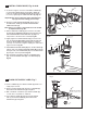
ADJUST SUPPLY STOP; Fig. 13
IMPORTANT: To avoid overowing, the SUPPLY STOP (3)
must never be opened to the point where the ow from
the valve exceeds the ow capacity of the xture. Valve is
designed to provide stated ush volume with a 25 GPM
ow rate.
1. Remove COVER (2) from SUPPLY STOP (3).Turn on
water supply 1/4 turn to 1/2 turn(CCW) and test for leaks.
Note: Unit may ush for approximately 5 to 10 sec. when
water is rst turned on.
2. Actuate the FLUSH VALVE by activating a ush.
3. Adjust SUPPLY STOP (3) after each ush until the
stated ush volume is achieved, no splashing occurs
and the xture is properly cleansed.
4. When adjustment is complete, reinstall COVER (2)
and tighten to ensure vandal-resistance.
12
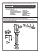
HOW TO RETROFIT OUR VALVE; Fig. 14
(Replaces Industry Standard Manual and Electronic
Valves)
Note: In most Retrots the wall escutcheon, supply
stop, cover tube and vacuum breaker do not have to
be replaced. If these items do need replacement they
must be purchased separately or order the complete
ush valve assembly from American Standard.
1. Remove COVER (1) from SUPPLY STOP (2) if installed.
Fig. 14.
2. Tu r n water supply off. Fig. 14.
3. Loosen SPUD COUPLING NUT (3). Unthread COUPLING
NUT (4) and VACUUM BREAKER COUPLING NUT (5).
Remove FLUSH VALVE (6).Fig. 4a.
4. Clean all threaded connections before installing the new
ush valve. Fig. 14a.
5. Refer to Sections 4, 5 and 6 to complete the retrot
installation. Fig. 14b.
13
LEFT OR RIGHT HAND INSTALLATION;
Fig. 15
1. The FLUSH VALVE can be installed either as a right
or left hand installation.
2. Orientate the FLUSH VALVE as shown in Fig. 13 to
desired position for a left or right hand installation.
NOTE: If it is necessary to change orientation of SMO
unit, use the provided collar wrench to loosen the
collar nut, rotate SMO unit 180 degrees and tighten
collar nut again.
Fig. 13
2
REMOVE COVER
CLOCKWISE CLOSES
CONTROL STOP
COUNTER-CLOCKWISE
OPENS CONTROL STOP
3
CLEAN
CONNECTIONS
2
Fig. 14 Fig. 14a Fig. 14b
1
4
5
3
6
Fig. 15
Right or Left Hand Installation
Left Hand Right Hand
M965831 (5/17)
7