
Installation Guide

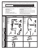


FOR AC-VERSION
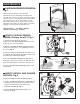
(MULTI HOOK-UP); Fig. 3, 3a, 3b
3
NOTE: For AC installation see “AC VERSION; Fig. 2b.”
Make power supply connection before mounting
ENCLOSURE (1) to wall.
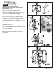
1. Remove COVERS from all ENCLOSURES (2). Fig. 3.
2. Remove SOLID BLACK INSERT (5) from left side of all
ENCLOSURES (2), except from Unit #1. Replace with
GRAY GROMMET (9). (Supplied with each Faucet). Fig. 3.
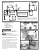
3. All Units: Connect the two 27" EXTENSION CABLES
(4) to the Faucet Sensor Cables. Feed the 27"
EXTENSION CABLE CONNECTORS (1, 1a) from the
Faucet through the top of ENCLOSURE (2). Fig. 3a.
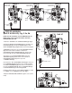
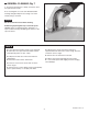
4. Connect one 27" EXTENSION CABLE (1) to the
SOLENOID (3). Fig. 3, 3a. Connect the second 27"
EXTENSION CABLE (1a) to the top of the
Y-CONNECTOR (8).
5. Connect the 10 ft. EXTENSION CABLE (6) to the top of
the Y-CONNECTOR (8). Feed the other end through the
two GRAY GROMMETS (9) and connect to the bottom of
the next Y-CONNECTOR (8). Place Y-CONNECTOR (8)
into ENCLOSURE (2) as shown Fig. 3a, 3b.
6. Repeat Steps above for each additional Unit, for a Max.
of 15 Units on one POWER SUPPLY (7). Fig. 3.
7. Replace ENCLOSURE COVERS. Tighten cover screws
firmly.
6
M968809 Rev.1.6
Unit #1
Unit #1
Unit #2 Unit #3
Fig. 3
Fig. 3a
1a
8
6
AC POWER SUPPLY
AC POWER
SUPPLY
10 ft. EXTENSION
CABLE
10 ft. EXTENSION
CABLE
FAUCET WIRE
CONNECTORS
4
SENSOR
CABLES
3
7
2
1
5
5
6 6 6
8 8
9
5
9
FAUCET WIRE
CONNECTORS
FAUCET WIRE
CONNECTORS
6
6
8
9
Fig. 3b