
Installations & Assembly


4
M965652 Rev. 1.7 (10/16)
2
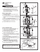
MOUNT CONTROL BOX; Fig. 2
1. DeterminelocationofCONTROLBOX(1). It must be located
with-inthe14"(356mm)by21"(533mm)shadedareashown
inFigure2inorderforelectricalconnectionsfromthespout
assembly to be made.
NOTE: CONTROL BOX SUPPLY HOSE IS 20". DISTANCE
BETWEEN WALL SUPPLY AND ENCLOSURE (1)
MUST BE TAKEN INTO CONSIDERATION.
2.RemovetapefromCONTROLBOXCOVER(2) and pull off
COVER(2).HoldtheCONTROLBOX(1) in desired
locationandmarkthefourmountingholelocationsas
shown.
NOTE: Find plastic bag containing 4 M5X16 screws to be
used for securing the CONTROL BOX COVER (1)
when installation is complete.
NOTE: For AC installation, make power supply connection
before mounting CONTROL BOX (1) to wall.
3.ItisrecommendedthattheCONTROLBOX(1) be
secured to a wall stud or cross brace within the wall using
theSCREWS(3)supplied.IftheCONTROLBOX (1) is to
be installed on tile or plaster walls, the ANCHORS (4) and
SCREWS (3) should be used.
3
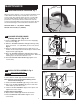
CONNECT SPOUT HOSE TO CONTROL BOX;
Fig. 3
1. Connect SUPPLY NUT (1)fromspouthosetonippleontop
ofENCLOSURE (2). Tighten with adjustable wrench to make
a water tight connection. Fig. 3.
4
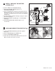
CONNECT WATER SUPPLY TO CONTROL
BOX AND WALL SUPPLY; Fig. 4, 4a
NOTE: If using the optional Mixing Valve, see sheet
#M968808 for installation instructions.
1. InsertFIBERWASHER (4) into SUPPLY NUT (1) on
CONTROLBOX (2).
2. ConnectFLEXIBLESUPPLYHOSE (3) to SUPPLY NUT (1)
onCONTROLBOX (2). Tighten to make a water tight
connection.Usetwowrenchestotightenifnecessary.Fig. 4.
3. ConnectFLEXIBLESUPPLYHOSE (3) directly to wall
supply.ConnectiononFLEXIBLESUPPLYHOSE (3)is3/8"
compression. Use adjustable wrench to tighten connection.
Donotovertighten.Fig. 4a.
Note:FLEXIBLESUPPLYHOSE(3) measures 20"from
thebottomoftheCONTROLBOX (2) base.Ifadditional
supply length is required, installer must purchase parts
separately.
Impor tant:IfFLEXIBLESUPPLYHOSE (3) is too long, loop to
avoid kinking.
Fig. 2
14"
(356mm)
3-3/4"
(96mm)
2-3/4"
(71mm)
3"
(76mm)
21"
(mm)
2
4
3
1
1
1
20"
(500mm)
MOUNTING HOLES
SUPPLIES
WASTE
ENCLOSURE
MOUNTING
HOLES
LAVATORY RIM OR
MOUNTING SURFACE
Fig. 3
1
2
1
3
3
Fig. 4
2
COLD WATER OR
TEMPERED
WALL SUPPLY
Fig. 4a
4