
Installation Guide


8
M965652 Rev. 1.9 (3/19)
A
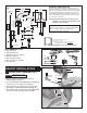
HAND WASH SENSOR OPERATION; Fig. 1
When the Sensor detects a user, the water immediately starts
to ow. Water ow will stop 2 seconds after user is out of
sensor range. The off delay allows the user to comfortably
move his hands without the ow cycling on and off. As a
precaution, a safety timer will turn off the water after the
sensor has been blocked for 59 seconds. The water will stay
off until the blockage is removed from the detection zone.
Detection Zone: 2" - 10" (50mm - 250mm)
Default: Set at Factory 6" (150mm)
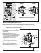
B
CHANGE SENSOR RANGE;
(Factory set at 6") Fig. 2, 2a
1. Remove CONTROL BOX. Disconnect Power Supply (1),
then reconnect. Fig. 2.
2. While the SENSOR CONTROL LED (2) is blinking slowly,
place your hand 1 - 2 in. (30-50mm) in front of the sensor.
Fig. 2a.
3. When the LED stops blinking and stays “ON”, move your
hand to the desired position and hold in place until the LED
begins to blink again. Fig. 2a.
4. Once the SENSOR CONTROL LED (2) begins to blink
again, remove your hand from the detection zone. When the
ashing stops, the detection distance is set.
5. Reinstall CONTROL BOX COVERS (2). Tighten cover
screws rmly.
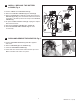
C
CLEAN FILTER ASSEMBLY; Fig. 3
1. Remove CONTROL BOX COVER.
2. Close SUPPLY STOP (13) with 4mm Hex wrench.
Note: Activate sensor to keep water owing out of
faucet while shutting off.
3. Unthread FILTER ASSEMBLY (6) using a 7/16" socket.
4. Pull out the FILTER ASSEMBLY (6), remove and clean
white debris cup and lter screen.
5. Install the FILTER ASSEMBLY (6) back in its place and
tighten with a 7/16" socket.
Caution: Do not over tighten.
6. Open SUPPLY STOP (13) with 4mm Hex wrench.
7. Reinstall CONTROL BOX COVER. Tighten cover
screws rmly.
Fig 1
5
6
4
10
3
DETECTION
ZONE
Fig. 2
1
Fig. 2a
1" - 2" (30mm - 50mm)
BLINKING LED
UP TO 10" (250mm)
BLINKING
LED
2
2
6
WHITE
DEBRIS
CUP
FILTER
SCREEN
•
•
•
•
•
•
•
•
•
•
•
•
•
•
•
•
•
•
•
•
•
•
•
•
•
•
•
•
•
•
•
•
•
•
•
•
•
•
•
•
•
•
•
•
•
•
•
•
•
•
•
•
•
•
•
•
•
•
•
•
•
•
•
•
•
•
•
•
•
•
•
•
•
•
•
•
•
•
•
•
•
•
•
•
•
•
•
•
•
•
•
•
•
•
•
•
•
•
•
•
•
•
•
•
•
•
•
•
•
•
•
•
•
•
•
•
•
•
•
•
•
•
•
•
•
•
•
•
•
•
•
•
•
•
•
•
•
•
•
•
•
•
•
•
•
•
•
•
•
•
•
•
•
•
•
•
•
•
•
•
•
•
•
•
•
•
•
•
•
•
•
•
•
•
•
•
•
•
•
•
•
•
•
•
•
•
•
•
•
•
•
•
•
•
•
•
•
•
•
•
•
•
•
•
•
•
•
•
•
•
•
•
•
•
•
•
•
•
•
•
•
•
•
•
•
•
•
•
•
•
•
•
•
•
•
•
•
•
Fig. 3
7/16" SOCKET
4mm HEX WRENCH
13
CAUTION
Before opening CONTROL BOX
disconnect AC power supply.
MAINTENANCE