
Instructions / Assembly


6
M965652 Rev. 1.7 (10/16)
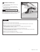
Fig. 2
10a
11
7
2
2
Fig. 2b
2
3
1
6
9
FROM ELECTRICAL BOX
WITH POWER SUPPLY
Fig. 2c
BLACK & WHITE
POWER
CONNECTIONS
15
13
CONNECTOR NOT
USED IN THIS
INSTALLATION
10b
14
4" ELECTRICAL BOX
OR EQUIVALENT BY
OTHERS
12
Fig. 2a
16
6
9
810
2
PLUG INTO
WALL OUTLET
7
B
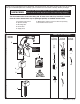
AC VERSION; Fig. 2
• PLUG-IN
• HARDWARE
Note: For AC installation, make power supply connection
before mounting CONTROL BOX (3) to wall.
1. RemoveCONTROLBOXCOVER(1). Feed the
EXTENSIONCABLES(2)fromtheFaucetthrough
thetopofCONTROLBOX(3).InstallCONNECTOR
LOCKINGDEVICE(16). Fig. 2.
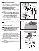
FOR AC PLUG-IN ONLY
2a.InsertPOWERCORD (8) throughPOWERSUPPLY
GROMMET (9) Fig. 2a.
3a.InsertPOWERCORD(8)throughsideGROMMET (6)
as shown. Connect it to the SINGLEACADAPTER (10).
Fig. 2a.
4a. Connect 27"EXTENSIONCABLES (2)toSOLENOID
CABLE (7) andPOWERCORD(8). Fig. 2a.
5a. Mount CONTROLBOX to wall. Reinstall CONTROLBOX
COVER(1). Tighten cover screws rmly.
6a.PlugACPOWERSUPPLYintowalloutlet.
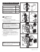
FOR AC HARDWIRE ONLY
2b.Insertoneendofthe10'EXTENSION(10a) through
POWERSUPPLYGROMMET(9). Fig. 2b.
3b. Insert 10'EXTENSION (10a) through side
GROMMET (6) as shown. Fig. 2b.
4b. Connect10’EXTENSION(10a)tosingleterminalof
SINGLEACADAPTER (11). Fig. 2b.
5b.Connect27"EXTENSIONCABLES(2) toSOLENOID
CABLE (7)andtotheavailableterminaloftheSINGLE
ACADAPTER(11).
6b. Mount CONTROLBOX (3) to wall. Reinstall CONTROL
BOXCOVER (1). Tighten cover screws rmly.
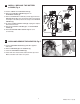
Contractor to supply ELECTRICAL BOX (12) and power
to POWER SUPPLY (13).
7b.MountPOWERSUPPLY (13) intoELECTRICAL
BOX (12). Connect White and Black connections to
POWERSUPPLYCONNECTIONS(14). Fig. 2c.
8b. Connect the10'EXTENSION(10b)tothePOWER
SUPPLYCABLE (15). Fig. 2c.
CAUTION
Disconnect AC power supply
before opening CONTOL BOX.
CAUTION: Use only American Standard supplied cable sets.
Usingnon-ASsuppliedcables,orcutting,splicingormodifying
any components will void the warranty.