
Installation Guide


9
M965646 REV. 2.1 (10/19)
3
Fig. 13
VIEW “A”
1
2
5
3
6
VIEW “A”
4
STANDARD BATTERY
D
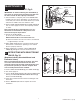
SET DETECTION RANGE
(If Required); Fig. 13 y 14
Note: The detection distance is preset and ideal for most
installations. Should an adjustment be required, follow
the steps below.
1. Loosen SET SCREW (1) with 2.5mm Hex Wrench (2) in
back of FLUSH VALVE COVER (3). Fig. 13a.
2. Rotate COVER (3) to the right and pull off. Fig. 13b.
3. Turn COVER (3) over and disconnect CABLE (4) from
BATTERY HOLDER (5). Fig. 13.
4. Keeping hands away from the sensor detection area,
reconnect the SENSOR (4) and quickly place the COVER
(3) on the valve. Do not secure the COVER (3) at this time.
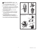
Note: You have 5 seconds to begin entering the program
code after power connection is made.
5. While the SENSOR CONTROL LED (1) is blinking slowly,
place your hand 1 to 2 in. (30-50mm.) in front of the sensor.
Fig. 14.
6. When the LED (1) stops blinking and stays “ON”, move your
hand to the desired position and hold in place until the LED
(1) begins to blink again. Fig. 14.
Note: Detection Zone is 400mm - 800mm.
(Factory Setting: 400mm)
7. Once the SENSOR CONTROL LED (1) begins to blink
again, remove your hand from the detection zone.
When the ashing stops, the detection distance is set.
8. Replace and secure COVER (3) onto valve.
9. Actuate the FLUSH VALVE:
A) Cover sensor with hand for 10 seconds.
NOTE: Stand outside of sensor detection area.
B) Remove hand from in front of the sensor; unit will
ush in approximately 3 seconds.
1
1
1" - 2" (30mm - 50mm
BLINKING LED
BLINKING LED
Fig. 14
DETECTION ZONE
400mm TO 800mm
(Factory Setting: 400mm)