
Installation Guide
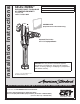


8
M965644 EN REV. 1.5 (9/15)
A
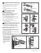
ADJUST STOP VALVE; Fig. 12
IMPORTANT: To avoid overowing, the STOP
VALVE (3) must never be opened to the point
where the ow from the valve exceeds the
draining ability of the xture.
1. After installation is complete, peel off the PROTECTIVE
FILM (1) from the sensor. Standing to one side, block the
sensor with your hand for 10 seconds.
Remove your hand and listen for audible “click” from
within the valve.
2. Remove STOP VALVE COVER (2) from STOP VALVE (3).
Turn on water supply 1/4 turn to 1/2 turn (CCW) and test
for leaks.
Note: Unit may ush for approximately 5 to 10 sec. when
water is rst turned on. If ow persists, turn water off and
repeat step #1 above.
3. Actuate the FLUSH VALVE:
A) Cover sensor with hand for 10 seconds.
NOTE: Stand outside of sensor detection area.
B) Remove hand from sensor detection area; unit will
ush in approximately 3 seconds.
4. Adjust STOP VALVE (3) after each ush until the stated
ush volume is achieved, no splashing occurs and the
xture is properly cleansed.
5. When adjustment is complete, replace STOP VALVE
COVER (2) and tighten to ensure vandal-resistance.
1
Fig. 12
2
CLOCKWISE CLOSES
STOP VALVE
3
COUNTER-CLOCKWISE
OPENS STOP VALVE
REMOVE COVER
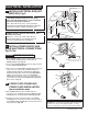
MAINTENANCE
Fig. 11
5
2
3
4
1
6
3
1
9
10'
Finished Wall
2" Diameter Hole
for Conduit
8
7
9
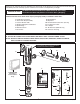
INSTALL CONDUIT, ESCUTCHEON
AND SENSOR CABLE; Fig. 11
1. Drill a 2" diameter hole (shown in Fig. 9) in the nished
wall for the CONDUIT (2).
2. Slide ESCUTCHEON (1) onto CONDUIT (2).
3. Thread CONDUIT (2) into COVER (4) and secure by
tightening LOCK NUT (5).
4. Make sure 10' EXTENSION CABLE (7), 27" EXTENSION
CABLE (3), CONNECTOR HOUSING (8), and CONDUIT (2)
are inserted through the 2" diameter hole in the wall.
5. Slide ESCUTCHEON (1) tight against nished wall and
secure by tightening SET SCREW (6).