
Installation Instructions


7
M965645 EN REV. 2.2 (10/19)
8a
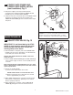
INSTALL CONDUIT,
ESCUTCHEON AND SENSOR
CABLE; Fig. 10
1. Drill a 2" diameter hole (shown in Fig. 10) in the nished
wall for the CONDUIT (2).
2. Pull 27" EXTENSION CABLE (3 ) through CONDUIT (2).
3. Slide ESCUTCHEON (1) onto CONDUIT (2).
4. For front installation, connect the 10' EXTENSION
CABLE (4) to the 27" EXTENSION CABLE (3). Secure
this connection with the CONNECTOR LOCKING
DEVICE (5) and place inside electrical box.
5. Slide ESCUTCHEON (1) tight against nished wall and
secure by tightening SET SCREW (6).
ELECTRICAL INSTALLATION
REMOTE INSTALLATION FOR POWER SUPPLY
Mount a 4" x 4" x 2-1/2" (102 x 102 x 64 mm),
ELECTRICAL BOX (1) (by others) within 10'
from the installed ush valve. See Fig. 10.
8
INSTALL ELECTRICAL BOX
(BY OTHERS); Fig. 10
FRONT INSTALLATION (with optional cover plate)
Note: The ELECTRICAL BOX (1) can be installed in
any location along the marked arc.
Cut a 105 x 105 mm (4-1/8" x 4-1/8") opening in nished
wall for ELECTRICAL BOX (1) (by others) and follow
installation template provided in box. See Fig. 10.
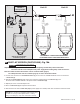
Fig. 9
BLACK & WHITE
POWER
CONNECTIONS
10' EXTENSION
1
2
7
NOTE: AC Transformer must be installed on the outside of
the Electrical Box.
10'
Finished Wall
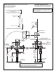
9
SUPPLY
(3/4" NPT)
86mm
(3-3/8")
SMALL END
1
2
3
4
5
6
7
8
(51mm) 2" DIA.
HOLE FOR
CONDUIT
305mm
(12" MAX.)
Fig.10 (TOP SPUD FIXTURE ILLUSTRATED)
7
INSTALL POWER SUPPLY AND
MAKE ELECTRICAL CONNECTIONS;
Fig. 9 (remote and front installation)
1. Connect Black and White power connections to AC
TRANSFORMER (1). Mount AC TRANSFORMER (1)
onto ELECTRICAL BOX (2).
2. Connect the 10' EXTENSION CABLE (sold seperately)
to the CONVERTER (7).
CAUTION
Ensure that the line power to bathroom
is OFF prior to making connections.
Electrical Box (by others) is only
required for Front Installation.