
Installation Instructions

10
M965645 EN REV. 2.2 (10/19)
1
2
4
3
5
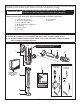
Fig. 13
1
B
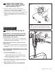
SET DETECTION RANGE
(if Required); Fig. 13 & 14
Note: The detection distance is preset and ideal for most
installations. Should an adjustment be required, follow the
steps below.
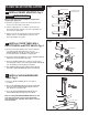
1. To remove the COVER PLATE (1), insert WIRE KEY (2)
(supplied) into the two holes located at the bottom of the
COVER PLATE (1). Push the WIRE KEY (2) up until it
releases the bottom clips. Pull the bottom edge away
and lift the COVER PLATE (1) off. Fig. 13.
2. Remove the connections from the CONNECTOR LOCKING
DEVICE (5). Disconnect the 27" EXTENSION CABLE (3)
from the 10' EXTENSION CABLE (4), and reconnect.
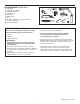
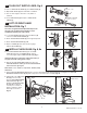
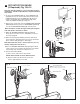
Note: You have 5 seconds to begin entering the program
code after power connection is made.
3. While the SENSOR CONTROL LED (1) is blinking
slowly, place your hand 1 to 2 in. (30-50 mm.) in front of
the sensor. Fig. 14.
4. When the LED (1) stops blinking and stays “ON”, move
your hand to the desired position from sensor and hold in
place until the LED (1) begins to blink again.
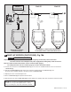
Note: Detection Zone is 400 - 800 mm (15-3/4"x 31-1/2").
(Factory Setting: 400 mm (15-3/4")
5. Once the SENSOR CONTROL LED (1) begins to blink
again, remove your hand from the detection zone. When
the ashing stops, the detection distance is set.
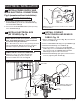
6. Actuate the FLUSH VALVE:
A) Cover sensor with hand for 10 seconds.
NOTE: Stand outside of sensor detection area.
B) Remove hand from detection area; unit will
ush in approximately 3 seconds.
1
1
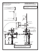
Fig. 14
1" - 2" (30 - 50 mm)
BLINKING LED
BLINKING LED
DETECTION ZONE
400 TO 800 mm (15-3/4" x 31-1/2")
(Factory Setting: 400 mm (15-3/4")