
Installation Instructions

3
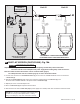
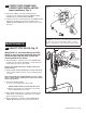
409 mm
(16-1/8")
Before
November
2017
406 mm
(16")
After
November
2017
292 mm
(11-1/2")
*-C-L-
-C-L-
117 mm
(4-5/8")
86 mm
(3-3/8)
73 mm
(2-7/8")
(3/4" NPT)
15˚
FINISHED WALL
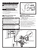
51 mm (2") HOLE
FOR CONDUIT
SEE DETAIL “A”
MANUAL
OVERRIDE
BUTTON
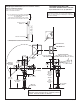
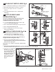
*Note: The Critical Line (-C-L-) on Vacuum
Breaker must typically be 6
" (152mm) above
fixture. Consult Codes for details.
305 mm MAX.
(12" MAX.)
TOP OF
FIXTURE
152 mm MIN.
(6") MIN.
76 mm MAX.
(3") MAX.
108 - 134 mm
(4-1/4" - 5-1/4")
DETECTION ZONE:
400 - 800 mm (15-3/4" – 31-1/2")
(FACTORY SETTING: 400 mm (15-3/4")
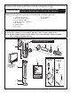
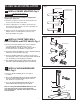
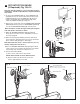
1. Installation Instructions
2. Flush Valve Body Assembly
3. Vacuum Breaker Tube
4. Spud Coupling Nut and Washers
5. Spud Flange
6. Wall Escutcheon
7. Cover Tube
8. Sweat Adapter
9. Stop Valve
GENERAL DESCRIPTION:
SELECTRONIC
®
PROXIMITY URINAL FLUSH VALVE
Exposed Flushometer for 3/4" Top Spud Fixtures
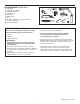
CAUTION: Use only American Standard supplied
transformers and cable sets. Using non-AS supplied
cables, or cutting, splicing or modifying any components
will void the warranty.
M965645 EN REV. 2.2 (10/19)
Roughing-in Dimensions (Front Installation Shown)
Right or Left Hand Installation
See (Section 5) for converting Flush
Valve to Left Hand Installation.
FINISHED TILE WALL
FINISHED PLASTER WALL
DETAIL “A”
4" (102 mm) SQ. x 3-1/2" (89 mm) DEEP ELECTRICAL BOX
Hubbel-RACO #256 OR EQUAL (BY CONTRACTOR).
4" (102 mm) SQ. BOX DEVICE COVER (PLASTER RING).
3/4" (19 mm) HIGH Hubbel-RACO #779 OR EQUAL
(BY CONTRACTOR).
NOTE: INSTALL PLASTER RING SO THAT SCREW
HOLES ARE ON THE LEFT AND RIGHT SIDE OF BOX.