
Installation Instructions

6
M965645 EN REV. 2.2 (10/19)
4
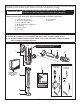
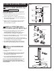
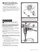
FLUSH OUT SUPPLY LINES; Fig. 6
1. Remove STOP VALVE COVER (1) from STOP VALVE (2).
2. Open STOP VALVE (2) with a at blade screwdriver.
3. Tu r n on water supply to ush line of any debris or
sediment.
4. Close STOP VALVE (2) and replace STOP VALVE
COVER (1).
5
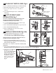
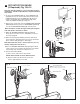
LEFT OR RIGHT HAND
INSTALLATION; Fig. 7
The unit is shipped with the adjustable tailpiece on
the right side. If needed, the orientation can be
modied by following the steps below.
1. Loosen SET SCREW (1) with 2.5mm Hex Wrench (4)
in back of FLUSH VALVE COVER (2).
2. Rotate FLUSH VALVE COVER (2) to the right and pull off.
3. Rotate FLUSH VALVE BODY (3) 180˚
4. Replace COVER (2) and rotate until key engages.
Tighten SET SCREW (1).
6
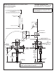
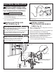
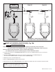
INSTALL FLUSH VALVE; Fig. 8, 8a
1. Insert ADJUSTABLE TAILPIECE (1) into the STOP
VALVE (2). Lubricate the O-RING (3) with water if
necessary. Lightly tighten COUPLING NUT (4). Fig. 8.
Important: Do not use lubricants (other than water) or
any type of thread sealing paste or tape.
2. Align the FLUSH VALVE BODY (5) directly above the
VACUUM BREAKER TUBE (7) and VACUUM BREAKER
COUPLING NUT (6). Fig. 8a.
Note: There is a +/- 13mm (+/- 1/2) on the 121mm (4-3/4)
dimension.
3. Pull the VACUUM BREAKER TUBE (7) up to meet the threaded FLUSH VALVE BODY (5), hand tighten the VACUUM
BREAKER COUPLING NUT (6). Align all components of the ush valve assembly. Fig. 8a.
4. Lightly tighten the COUPLING
NUT (4) connection rst,
then the VACUUM BREAKER
COUPLING NUT (6) and
nally the SPUD COUPLING
NUT (8). Once alligned
correctly, use a wrench to
tighten couplings to make
water tight connections.
Fig. 8a.
1
CLOCKWISE CLOSES
STOP VALVE
COUNTER-CLOCKWISE
OPENS STOP VALVE
REMOVE COVER
Fig. 6
2
2
4
Fig. 7
4
KEY
2
2
1
3
180˚
2
1
7
8
6
5
4
121mm, +/-13 mm
(4-3/4)(+/-1/2)
Fig. 8
Fig. 8a
2
4
1
3