
Installation Instructions


9
M965645 EN REV. 2.2 (10/19)
A
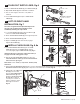
ADJUST STOP VALVE; Fig. 12
IMPORTANT: To avoid overowing, the STOP
VALVE (3) must never be opened to the point
where the ow from the valve exceeds the
draining ability of the xture.
1. After installation is complete, peel off the PROTECTIVE
FILM (1) from the sensor. Standing to one side, block the
sensor with your hand for 10 seconds.
Remove your hand and listen for audible “click” from
within the valve.
2. Remove STOP VALVE COVER (2) from STOP VALVE (3).
Turn on water supply 1/4 turn to 1/2 turn (CCW) and test
for leaks.
Note: Unit may ush for approximately 5 to 10 sec. when
water is rst turned on. If ow persists, turn water off and
repeat step #1 above.
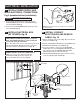
3. Actuate the FLUSH VALVE:
A) Cover sensor with hand for 10 seconds.
NOTE: Stand outside of sensor detection area.
B) Remove hand from sensor detection area; unit will
ush in approximately 3 seconds.
4. Adjust STOP VALVE (3) after each ush until the stated
ush volume is achieved, no splashing occurs and the
xture is properly cleansed.
5. When adjustment is complete, replace STOP VALVE
COVER (2) and tighten to ensure vandal-resistance.
1
Fig. 12
2
CLOCKWISE CLOSES
STOP VALVE
3
COUNTER-CLOCKWISE
OPENS STOP VALVE
REMOVE COVER
MAINTENANCE
9
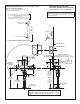
COVER PLATE FRAME AND
COVER PLATE INSTALLATION
(front installation); Fig. 11
1. After power supply is remotely installed and wire
connections are completed, install the COVER PLATE
FRAME (1) onto the ELECTRICAL BOX (2).
2. Install the two tabs on the back side of the COVER PLATE
(3) into the two Slots located on the top edge of the
COVER PLATE FRAME (1). Push on bottom until it snaps
into place.
CAUTION: Use only American Standard supplied transformers
and cable sets. Using non-AS supplied cables, or cutting,
splicing or modifying any components will void the warranty.
Fig.10a
TABS
SLOT
SLOT
1
3
2
Fig. 9
BLACK & WHITE
POWER
CONNECTIONS
10' EXTENSION
1
2
7
Fig. 11