
Installation Instructions


5
M965644 EN REV. 2.3 (10/19)
1
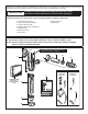
INSTALL SWEAT ADAPTER; Fig. 3
Note: Install Optional Sweat Adapter (Supplied) for
copper pipe supply line.
1. Measure the distance (A) from the nished wall to the
center of the inlet spud on the xture.
2. Cut the supply pipe 1-1/4" (A-B=C) shorter than the
measurement taken in Step 1. File any rough edges off
the end of the supply pipe.
3. Clean the end of the supply pipe. Push the threaded
Adapter until it is seated against the internal stop.
Sweat the Adapter to the pipe.
2
INSTALL COVER TUBE, WALL
ESCUTCHEON and STOP VALVE; Fig. 4
1. Measure from nished wall to rst thread of Adapter
or threaded supply pipe (dimension “X”). Cut
COVER TUBE (1) to length (X). Apply Teon Tape to
the threaded end of the Adapter or supply pipe.
2. Push WALL ESCUTCHEON (2) onto the COVER TUBE (1).
Slide both onto the SUPPLY PIPE (3).
3. Push the COVER TUBE (1) in to expose the threads of
the supply pipe. With a wrench, thread the STOP VALVE (4)
onto the SUPPLY PIPE (3). Align and tighten.
4. Pull COVER TUBE (1) against STOP VALVE (4) and
push WALL ESCUTCHEON (2) against nished wall.
3
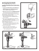
INSTALL VACUUM BREAKER
TUBE; Fig. 5
1. Place the SPUD FLANGE (1) over the spud on
the Fixture.
2. Place FRICTION WASHER (3) and SEAL WASHER
(4) inside SPUD COUPLING NUT (2) and thread
onto Spud. Do not tighten fully.
3. Insert the VACUUM BREAKER TUBE (5) into the
SPUD COUPLING NUT (2) and push it down.
Note: If cutting VACUUM BREAKER TUBE (5) to size,
note that Critical Line (C/L) on Vacuum Breaker
must typically be 6" (152mm) above xture. Consult
Code for details.
CAUTION
Turn water supplies off before
beginning
CENTER LINE OF
FIXTURE SPUD
FINISHED WALL
FILE EDGES
SOLDER
ADAPTER
Fig.3
ADAPTER
32mm
(1-1/4")
A
(A-B)=
B
C
CLEAN
1
1
4
2
3
Fig. 4
TEFLON TAPE
FINISHED WALL
X
X
2
1
2
3
4
5
1-1/2" TOP SPUD
Fig. 5
FLUSH VALVE INSTALLATION