
Installation & Assembly


9
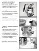
GENERAL CLEANING; Fig. 13
G
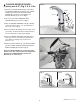
1. Remove the FAUCET SPOUT (1) by unthreading the
LEVER SCREW (2) and pulling off the LEVER
HANDLE (3). Unthread the FAUCET SPOUT
SCREW (4) at the back of the FAUCET. Pull FAUCET
SPOUT (1) up and off. See Fig. 2 in this section.
2. Replace LEVER HANDLE and rotate
counter-clockwise to its stop position (100% cold).
Remove HANDLE.
3. Pull out LIMITER STOP (1) from the VALVE STEM (2).
4. Rotate LIMITER STOP (1) 180 degrees and insert
back onto VALVE STEM (2).
5. Replace FAUCET SPOUT (1) and LEVER HANDLE
(3). Install LEVER HANDLE SCREW (2), FAUCET
SPOUT SCREW (4) and tighten. See Fig. 2 in this
section.
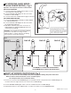
CHANGE HOT LIMIT SETTING
FROM 95% TO 85%; Fig. 12
F
3
9
8
1
2
ROTATE 180˚
SLOT
SLOT
Fig. 12
Fig. 13
FAQ'S
Q: How will I know if the battery needs to be replaced?
A: Valve will not open and sensor will continuously blink 2 times interrupted by a pause for up to 7 days.
Q: Why has the flow rate of the faucet reduced significantly?
A: The filter assembly, flow regulator or areator/spray may be clogged. Check and clean. Refer to Start-up/Maintenance,
sections C, D and E.
Q: Why doesn’t the water flow out of faucet when I'm within the sensor detection zone?
A: Battery may need replacement. Check. If sensor continuously blinks 2 times interrupted by pause, replace battery
or call (844) CRT-TEAM / (844) 278-8326.
Q: What is the normal operating pressure range?
A: Faucet will operate with supply pressures ranging from 20-80 psi.
CAUTION
1. Only use a damp, soft cloth to clean the spout and
the sensor.
2. For tougher dirt, use a soft cloth with diluted dish
washing detergent. Wipe the area using a wet cloth
and dry using a soft cloth.
Do not scratch the sensor when cleaning.
Avoid using any abrasives or harsh detergents
or chemicals.
M965654 Rev. 2.2 (12/17)