
Installation & Assembly


Important: Turn off power to outlet or electrical box.
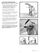
FOR PLUG-IN VERSION;
1. Connect PLUG-IN AC POWER SUPPLY (2) to one end
of the SINGLE AC ADAPTER (6).
2. Connect SENSOR CABLE (4) to the other end of the
SINGLE AC ADAPTER (6).
3. Connect PLUG-IN AC POWER SUPPLY (2) to wall outlet.
FOR HARD-WIRED VERSION;
1. Connect 10' EXTENSION CABLE (1) to HARD-WIRED
AC TRANSFORMER (3).
2. Connect SENSOR CABLE (4) to the other end of the
10' EXTENSION CABLE (1).
3. Make Black and White power line connections to
HARD-WIRED AC TRANSFORMER (3) and mount
on ELECTRICAL BOX (5).
Fig. 2
4
Unit #1
(Already Installed)
Fig. 3
Unit #2 Unit #3 Unit #4
1
2
4
3
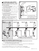
MAXIMUM OF 15 UNITS PER TRANSFORMER.
10' MAXIMUM CABLE LENGTH BETWEEN UNITS.
MULTI-AC VERSION (DAISY-CHAIN); Fig. 3
Important: Disconnect the first unit’s Y-Adapter from power supply before making daisy-chain connections.
Note: For Unit #1 electrical instructions, refer to section B (page 3).
For subsequent Units, refer to instructions below...
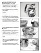
C
1. Connect one end of the 10' EXTENSION (1) to the available terminal of the previous unit’s Y-ADAPTER (2), and
the other end to the single terminal of the current unit’s Y-ADAPTER (3).
2. Connect SENSOR CABLE (4) to either of the two available terminals of Y-ADAPTER (3).
3. Repeat Steps above for each additional Unit, for a Max. of 15 Units on one AC POWER SUPPLY.
M965654 Rev. 2.2 (12/17)
AC VERSIONS (HARD-WIRED /
PLUG-IN POWER SUPPLY) ; Fig. 2
B
CAUTION: Use only American Standard supplied
transformers and cable sets. Using non-AS
supplied cables, or cutting, splicing or modifying
any components will void the warranty.
Do not connect power to transformer
until installation of faucet is complete.
Recommended Electrical Box or Equivalent
by others 4” (102mm) SQ. X 2-1/2” (64mm)
DEEP 2-GANG ELECTRICAL BOX Appleton
#4SD1 OR EQUAL (BY OTHERS).
BLACK & WHITE
POWER
CONNECTIONS
Fig. 2
6
4
2
3
5
1
1
WALL
OUTLET
4" CONTROL BOX
OR EQUIVALENT BY
OTHERS (6)
BLACK & WHITE
POWER
CONNECTIONS
10' EXTENSION