
Dimensions Guide


M968508 (11/15)
2a
10
3
5
5/16'' MIN.
MOUNTING SURFACE
11
11
1
2
3
1
2
2
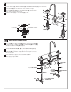
Insert VALVES (5) into mounting holes from underside of ledge.
Install LOCKNUTS (1), BRASS WASHERS (2) and RUBBER WASHERS (3) onto valve shanks.
Place RUBBER RING (11) into DECK ADAPTERS (10) and thread onto
valves until snug against internal stop.
Tighten LOCKNUT (1) to secure VALVE (5) position.
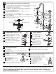
VALVE ASSEMBLY WITH FLEXIBLE HOSE VALVE CONNECTIONS
HOT
COLD
5
8
7
5
10
MOUNTING
LEDGE
11
10
Connect HOT water supply to inlet of left SHANK and COLD
water supply to right SHANK.
Press TEE (8) onto SPOUT SHANK (5) making certain that the O-RING (9)
is properly seated on SPOUT SHANK (5). Push COUPLING (4) into TEE (8)
and attach to SPOUT SHANK (5) and tighten.
Thread HOSE CONNECTOR (6, 6A) to VALVE CONNECTIONS (7, 7A).
Connect water supply to VALVE BODIES (1,1A) with 1/2" IPS FLEXIBLE
SUPPLIES (2) (not included. Use adjustable wrench to tighten connections.
Do not over tighten.
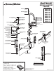
WATER SUPPLY CONNECTIONS
HOT
COLD
FERRULE
COMPRESSION
NUT
COUPLING
NUT
FLEXIBLE
SUPPLIES
1
1A
3/8 O.D.
BULL-NOSE
RISERS
1/2" PIPE THREAD
3/8 COMPRESSION
CONNECTION
2
3
4
5
7
6
6A
7A
9
8