
Specification


M965622
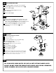
Operate LIFT KNOB (1) to verify that STOPPER (2) opens and
closes.
Note: If STOPPER (2) does not open and close properly, refer
to the “troubleshooting section” of these instructions.
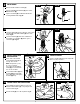
CHECK OPERATION OF POP-UP
8
3
ATTACH CABLE CONNECTOR
7
2
1
1-1/4” O.D.
2
1
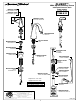
Faucet supplies are 20" long from faucet base.
Note: If additional supply length is required, installer
must purchase additional parts separately.
Important: If FLEXIBLE SUPPLIES (1, 2) are to long,
loop to avoid kinking.
Connect 1-1/4" O.D. tailpiece on POP-UP DRAIN to
waste outlet.
Connect FLEXIBLE SUPPLIES (1, 2) directly to wall supplies.
Connection on fitting supplies is 3/8" compression. Connect
FLEXIBLE SUPPLY (1) (Marked with a Red Band) to the Left wall supppy and
FLEXIBLE SUPPLY (2) (Marked with a Blue Band) to Right wall supply.
9
Connect the VALVE HOSES (3, 3a) to SPOUT TEE (4).
Use adjustable wrench to tighten connections.
Do not over tighten.
MAKE WATER SUPPLY AND WASTE CONNECTIONS
Fig. A. Fig. B.
WASTE
OUTLET
HOT
COLD
1
3
3a
4
2
Blue Stripe
(C0LD)
Red Stripe (HOT)
Thread CABLE CONNECTOR (1) clockwise
onto CABLE ATTACHMENT POINT (2) and
hand tighten. Fig. A.
Your new POP-UP DRAIN installation is
now complete. Fig. B.
Note: Tailpeice on pop-up drain is 1-1/4” O.D.
Fig. B.