
Installation Guide

- 2 -
3
M965723 Rev. 1.1 (7/16)
4
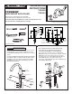
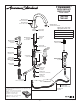
INSTALL HANDLES
VALVE ASSEMBLY
FOR FITTING
LESS SPRAY
11
10
2
HOT
COLD
12
13
7
6
8
8a
5
13
12
3
4
4
MOUNTING
SURFACE
10
9
9
1
2
4
5/16'' MIN.
MOUNTING
SURFACE
11
1
8
7
1
2
4
5
1
3
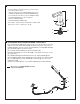
LEVER HANDLE
FLAT BLADE
SCREWDRIVER
(Figure A)
• Install LOCKNUTS (1) and RUBBER WASHERS (2) onto valve shanks.
• Push TUBING (3) ends into VALVE (4) side outlets. Insert VALVES (4)
into mounting holes from underside of ledge.
• Press TEE (5) onto SPOUT SHANK (6) making certain that the O-RING
(7) is properly seated on SHANK (6). Push COUPLING (8 or 8a) into
TEE (5) and attach to SPOUT SHANK (6) and tighten. For 7430.901
use a 10 mm (3/8") hex key.
• Threads of VALVE BODY (4) should extend at least 5/16 inch above
MOUNTING SURFACE (11). If necessary, adjust LOCKNUT (1).
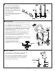
• Place RUBBER RING (10) into ESCUTCHEON ADAPTERS (9) and
thread onto valves until snug against internal stop.
• Tighten LOCKNUT (1) to secure VALVE (4) position with channel locks.
• Slide FERRULE (12) and COUPLING NUT (13) to outlet of VALVE (4)
and tighten COUPLING NUT (13) rmly.
• Connect HOT water supply to inlet of
left VALVE and COLD water supply to
inlet of right VALVE using appropriate
connector.
• Push ADAPTER (1) on VALVE STEM (2). Tighten STEM SCREW
(3) with a at blade to secure ADAPTER (1). Figure A.
• Find correct position of HANDLE ASSEMBLY (4) by adjusting
male teeth on ADAPTER (1) to female teeth in HANDLE (4).
• Push HANDLE ASSEMBLY (4) onto DECK ADAPTER (5)
until snug against mounting surface.
2
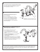
PREPARE TUBE AND TEE ASSEMBLY
• Prepare TUBE and TEE ASSEMBLY (1)
to t center to center VALVE (2) location
(between 6-1/2" and 12"). If necessary, cut
and/or bend TUBING carefully. Make sure
tube bend is close to the TEE (1) so that it
will not effect the compression joint at the
VALVE CONNECTION.
• Remove COUPLING NUT (3) and FERRULE
(4) from each VALVE (2) and slide onto
TUBING (5).
4
2
3
1
3
4
ADJ. 6-1/2" TO 12"
5
VALVE inlet is 3/4-inch NPT male.
NOTE
MOUNTING
SURFACE