
Installation Sheet


DECK MOUNT
BATH FILLER
PORTSMOUTH
™
*Wrench
Certified to comply with ANSI A112.18.1M
Recommended Tools
*Supplied with Fitting
*Hex key
Turn off hot and cold water
supplies before beginning.
CAUTION
1
2
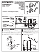
Insert SPOUT SHANK (2) through center hole of MOUNTING LEDGE.
Make sure that the RUBBER RING (1) is properly seated in RECESS
of SPOUT BASE.
Assemble RUBBER WASHER (3) and BRASS WASHER (4) onto
SHANK (2). From underside of ledge secure SPOUT (6) into position
with LOCKNUT (5).
SPOUT ASSEMBLY
PREPARE TUBE AND TEE ASSEMBLY
4
2
3
1
3
4
Prepare TUBE and TEE ASSEMBLY (1) to fit center to center
VALVE (2) location (between 6-1/2" and 12"). If necessary,
cut and/or bend TUBING carefully. Make sure tube bend is
close to the TEE (1) so that it will not effect the compression
joint at the VALVE CONNECTION.
Remove COUPLING NUT (3) and FERRULE (4) from each
VALVE (2) and slide onto TUBING (5).
5
Flat Blade Screwdriver
Adjustable Wrench
Channel Locks
VALVE inlet is
3/4-inch NPT male.
NOTE
ROUGHING-IN DIMENSIONS
MOUNTING
SURFACE
Installation
Instructions
7420.900
7420.901
Series
7420.920
7420.921
Series
Tubing Cutter
RECESS
6
1
3
5
2
4
MOUNTING
SURFACE
6-1/2" to 12"
(165mm to 305mm)
Install RUBBER RING (1) into recess of spout base.
M965027 REV.1.3
Thank you for selecting American-Standard...
the benchmark of fine quality for over 100 years.
To ensure that your installation proceeds smoothly--
please read these instructions carefully before you begin.
MOUNTING
SURFACE
2-1/4" D.
(56mm) D.
CROSS HANDLE
LEVER
HANDLE
7-7/8"
(199mm)
7-7/8"
(200mm)
4-7/8"
(125mm)
3-3/16"
(81mm)
2-7/8"
(73mm)
6-1/2" to 12"
(165mm to 305mm)
2-5/8" D.
(66mm) D.
1-1/2 MAX.
(38mm) MAX.
1-3/16" MAX.
(30mm) MAX.
1-3/16 D.
(30mm) D.
3'
(76mm)
(H)
(C)
1-1/8 D.
12 MAX.
(305mm)
2-1/16" D.
(52mm) D.
1-1/16 D.
(27mm) D.
3/4-14 MALE
N.P.T. INLETS
8-1/4"
(210mm)