
Installation Instructions


7
M965754 Rev. 1.7 (7/18)
B
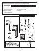
REPLACE BATTERY; Fig. 5, 6
1. Remove COVER SCREW (1) and lift COVER (15) off.
2. Disconnect SENSOR CABLES (6) and (7) from the
BATTERY and SOLENOID VALVE. (Fig. 6)
3. Push BATTERY (17) forward and Pull it out. (Fig. 5)
4. Replace the new battery with the same placement.
(Insert terminal side rst)
C
CHANGE SENSOR RANGE;
Fig. 5, 6
1. Remove the COVER SCREW (1).
2. Remove the COVER (15).
3. Disconnect the BLACK POWER SUPPLY CONNECTOR
(7) and reconnect. Fig. 6.
4. While the SENSOR CONTROL LED (9) is blinking slowly,
place your hand 1 - 2 in. (25.4-50.8mm) in front of the
sensor.
5. When the LED stops blinking and stays “ON”, move your
hand to the desired position and hold in place until the
LED begins to blink again.
6. Once the SENSOR CONTROL LED (9) begins to blink
again,
remove your hand from the detection zone. When the
ashing stops, the detection distance is set.
7. Reassemble the COVER (15) and secure it with COVER
SCREW (1).
D
ADJUST HOT LIMIT STOP;
Fig. 7, 9
To reduce the amount of hot water that can mix with cold, the
installer can adjust hot limit stop (Four different settings).
1. Rotate LEVER HANDLE (3) counter-clockwise to its stop
position (100% cold).
2. Remove LEVER SCREW (5) and pull off the LEVER
HANDLE (3).
3. Pull out LIMIT STOP (1) from the VALVE STEM (5).
4. Rotate LIMIT STOP (1) between the shaded area and
insert back onto VALVE STEM (5).
5. Each notch on the LIMIT STOP (1) will reduce the amount
of hot water by approximately 3%. For example, the 2nd
notch will have 97% of maximum temp, the 3rd notch will
have 94% and the fourth will be 91%.
6. Replace LEVER HANDLE (3), LEVER HANDLE SCREW
(5) and tighten.
15
16
2
1
4
9
14
7
Fig. 5
Fig. 6
6
12
17
1
2
Fig. 7