
Installation Guide


6
M965754 Rev. 1.7 (7/18)
D
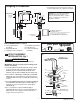
MAKE WATER SUPPLY
CONNECTIONS; Fig. 4
1. Turn off hot and cold water supplies before beginning.
2. Install INLINE FILTER (3) on each wall supply outlet. Be sure that
INLINE FILTER (3) is inserted in the correct direction.
(See Illustration)
3. Connect HOT FLEXIBLE SUPPLY (marked with red stripe) (1) to
INLINE FILTER (3) on hot water control stop (4). Connect COLD
FLEXIBLE SUPPLY (marked with blue stripe) (2) to INLINE FILTER
(3) on cold water control stop (5). Use adjustable wrench to tighten
connections. Do not over tighten.
4. Faucet supplies are 24" long from faucet base.
Note; If additional supply length is required, installer must
purchase those parts separately.
Important; If SUPPLY HOSES (1, 2) are too long, loop as
illustrated to avoid kinking.
Fig. 4
Fig. 5
DETECTION
ZONE
PROTECTIVE FILM
IMPORTANT: Do not
use sealent on threads
1
2
3
COLD
HOT
(3) INLINE
FILTER
Fig. 1
Installation Instructions
(In Toronto Area only: 1-905-3061093)
SELECTRONIC™
Thermostatic Mixing Valve
Certified to comply with ASME A112.18.1M
© 2005 American Standard
M968808
To learn more about American Standard Faucets visit our website at: www.us.amstd.com or U.S.
customer's e-mail us at: faucetsupport@amstd.com
For Parts, Service, Warranty or other Assistance,
please call
1-800-442-1902 (In Canada: 1-800-387-0369)
NOTE TO INSTALLER: Please give this manual to the customer after installation.
(In Toronto Area only: 1-905-3061093)
605XTMV
Specifications
Installation
Adjust Temperature
Service
Replacement Parts
1
2
3
3
4
No. M968808
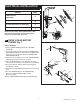
HOT
SUPPLY
COLD
SUPPLY
TEE
FITTING
Optional Mixing Valve
(Sold Separately)
TEMPERED
WATER SUPPLY
COLD
WATER
5
4
Fig. 6
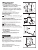
1
9
8
7
5
3
E
INSTALL OPTIONAL MIXING VALVE; Fig. 5
Note: An optional Thermostatic Mixing Valve (sold separately) may
be installed on faucets 775X.1XX & 775X.2XX in addition to Above
Deck Mixing valve. See setup diagram Fig. 5.
Te e tting is not supplied with Faucet or Thermostatic Mixing valve and
must be purchased separately. If faucet inlet hoses will not reach water
supplies, longer hoses must be purchased separately.
For complete detailed installation and operating instructions, see
installations instructions (No. M968808) supplied with Thermostatic
Mixing Valve.
F
REMOVE MIXING HANDLE
FOR FAUCETS PURCHASED AFTER OCTOBER 2019 (FIG. 6)
Note: Before removing the handle, preset the desired water temperature
and while disassembling make sure to keep the SHAFT EXTENSION (8)
in place.
1. Unthread SET SCREW (3) and remove HANDLE (5).
2. Remove LIMIT STOP (1).
3. Using a Slotted screwdriver unthread SCREW (7) and remove
SHAFT EXTENSION (8).
Note: Hold the extension in place while unthreading the screw.
4. Install CAP (9) onto the Body and press until you hear a click.
Note: Sharper side faces towards the back of the body.
MAINTENANCE
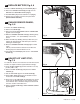
A
HAND WASH SENSOR OPERATION; Fig. 1
REMOVE PROTECTIVE FILM FROM SENSOR EYE WHEN
INSTALLATION IS COMPLETE.
When the Sensor detects a user, the water immediately starts to ow.
Water ow will stop 1.5 seconds after user is out of sensor range. This
Comfort delay allows the user to comfortably move their hands without
the water turning off.
As a precaution, a Safety Timer will turn off the water, after the sensor
has been blocked for 59 seconds. The water will stay off until the
blockage is removed from the detection zone.
The Comfort and Safety time settings can be adjusted using the
Optional Remote Control (605XRCT).