
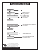
Installation Guide

7
M965754 (9/16)
B
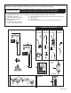
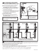
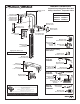
REPLACE BATTERY; Fig. 5, 7
1. Remove COVER SCREW (1) and lift COVER (15) off.
2. Disconnect SENSOR CABLES (6) and (7) from the
BATTERY and SOLENOID VALVE. (Fig. 7)
3. Push BATTERY (17) forward and Pull it out. (Fig. 5)
4. Replace the new battery with the same placement.
(Insert terminal side rst)
C
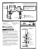
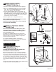
REPLACE SENSOR; Fig. 5, 6, 7
1. Remove COVER SCREW (1) and lift COVER (15) off.
2. Disconnect SENSOR CABLES (6) and (7) from the
BATTERY and SOLENOID VALVE. (Fig. 7)
3. Remove the AERATOR RETAINER SCREW (2) and
BODY FIXATION SCREW (3). (Do not remove SPOUT
TUBE 16)
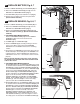
4. FOR ABOVE DECK MIXING FAUCETS
Remove FIXATION SCREW (13). Pull the HANDLE
ASSEMBLY (11) to remove the shaft from the
MANIFOLD (14).
5. Lift BODY (12) off of MANIFOLD (14).
6. Remove SENSOR (9) by carefully pushing on the face
of the sensor. Once removed, peal the SENSOR
ADHESIVE off of the BODY and clean the remaining
residue.
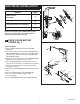
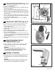
7. To install the new SENSOR, peal the paper liner from the
double sided tape and carefully place the SENSOR in its
original position so that the WIRES point upward. Press
and hold the sensor for 5 - 10 seconds to ensure it sticks
properly.
Note: To prevent damage to the wires, verify that they
are tucked inside the hooks which are located on both
sides of the sensor.
8. FOR ABOVE DECK MIXING FAUCETS
Slide SPOUT (12) over the MANIFOLD (14) being careful
to avoid interference between the SPOUT TUBE (16) and
SENSOR (9). Tighten the BODY FIXATION SCREW (3).
Insert HANDLE ASSEMBLY (11) into the MANIFOLD (14)
and secure it with FIXATION SCREW (13). Move the
SPOUT TUBE (16) and AERATOR RETAINER (2) into
position and tighten the AERATOR RETAINING SCREW
(2) to secure the assembly. Reconnect SENSOR
CABLES (6 and 7) to the BATTERY and SOLENOID
VALVE. Install COVER (15) and secure it with COVER
SCREW (1). Tuck extra lengths of wire in the empty
space located above FIXATION SCREW (13)
9. Slide SPOUT (12) over the MANIFOLD (14) being careful
to avoid interference between the SPOUT TUBE (16) and
SENSOR (9). Tighten the BODY FIXATION SCREW (3).
Move the SPOUT TUBE (16) and AERATOR RETAINER
(2) into position and tighten the AERATOR RETAINING
SCREW (2) to secure the assembly. Reconnect
SENSOR CABLES (6 and 7) to the BATTERY and
SOLENOID VALVE. Install COVER (15) and secure it
with COVER SCREW (1). Tuck extra lengths of wire in
the empty space located above FIXATION SCREW (13)
15
16
2
1
4
9
14
3
13
7
Fig. 5
Fig. 6
Fig. 7
12
11
10
6
12
17