
Installation Guide

8
D
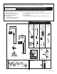
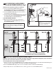
CHANGE SENSOR RANGE; Fig. 5, 6, 7
1. Remove the COVER SCREW (1).
2. Remove the COVER (15).
3. Disconnect the BLACK POWER SUPPLY CONNECTOR (7)
and reconnect. Fig. 7.
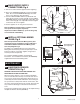
4. While the SENSOR CONTROL LED (9) is blinking slowly,
place your hand 1 - 2 in. (25.4-50.8mm) in front of the sensor.
5. When the LED stops blinking and stays “ON”, move your hand
to the desired position and hold in place until the LED begins
to blink again.
6. Once the SENSOR CONTROL LED (9) begins to blink again,
remove your hand from the detection zone. When the ashing
stops, the detection distance is set.
7. Reassemble the COVER (15) and secure it with COVER
SCREW (1).
E
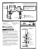
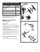
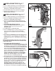
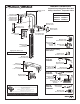
ADJUST HOT LIMIT STOP; Fig. 12, 14
To reduce the amount of hot water that can mix with cold, the
installer can adjust hot limit stop (Four different settings).
1. Rotate LEVER HANDLE (3) counter-clockwise to its stop
position (100% cold).
2. Remove LEVER SCREW (5) and pull off the LEVER
HANDLE (3).
3. Pull out LIMIT STOP (1) from the VALVE STEM (5).
4. Rotate LIMIT STOP (1) between the shaded area and insert
back onto VALVE STEM (5).
5. Each notch on the LIMIT STOP (1) will reduce the amount of
hot water by approximately 3%. For example, the 2nd notch will
have 97% of maximum temp, the 3rd notch will have 94% and
the fourth will be 91%.
6. Replace LEVER HANDLE (3), LEVER HANDLE SCREW (5)
and tighten.
F
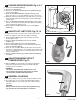
ADJUST MAXIMUM OUTLET
TEMPERATURE; Fig. 13
1. With the COVER off, the installer can reduce the maximum
mixed water temperature by turning the VALVE CAP (4)
clockwise with a screwdriver.
WARNING
• Do not turn the VALVE CAP (4) More than 1 turn.
• The maximum mixed water temperature can not be
increased due to ASSE 1070 requirements.
G
GENERAL CLEANING
1. Only use a damp, soft cloth to clean the spout and the sensor.
2. For tougher dirt, use a soft cloth with diluted dish washing
detergent. Wipe the area using a wet cloth and dry using a
soft cloth.
CAUTION
Do not scratch the sensor when cleaning. Avoid using
any abrasives or harsh detergents or chemicals.
M965754 (9/16)
Fig. 12
Fig. 13
Fig. 14
4
1
2
3
5