
Installation Guide


7
GROUNDING INSTRUCTIONS
Installation Location
Water Supply
Checking the Bathroom
The dimensions required for mounting this product on a toilet are shown in the gure below. Check to
make sure there is sufficient space inside the bathroom and that there are no obstructions.
Use only the tap water line to supply water to this product. The use of any other type of water i.e. ground
water or well water may reduce functionality of product.
The tap water pressure must be 8.5 to 106.7 psi
(0.06 to 0.74 MPa, 0.6 to 7.5 kgf/cm
2
).
In order to prevent damage to the electronic components, install this product at a location that
minimizes the possibility of it getting wet. In extremely humid conditions, provide adequate ventilation by
operating an exhaust fan or opening a window or door.
Remote receiver
Rated voltage
AC120V
To connect ceramic
water tank
Water valve G15/16
Power line length
47-1/4" (1200mm)
Hose length
27-9/16" (700mm)
Finished oor
Finished oor
Dimension range
of adjustment
Power Plug
(Recommended
position)
11-1/4"
(286mm)
2-3/16"
(56mm)
11-1/4"
(286mm)
2-3/16"
(56mm)
7-11/16"
(195mm)
7-11/16"
(195mm)
21-1/16"
(535mm)
17-3/16 - 20-3/16"
(437 - 513mm)
5-1/8 - 8-7/16"
(130 - 214mm)
9-13/16 - 13-3/4"
(249 - 349mm)
9-1/2"
(241mm)
6"
(152mm)
2-3/8"
(60mm)
4-3/8"
(111mm)
6-13/16"
(173mm)
7-15/16"
(202mm)
14-7/8"
(378mm)
9-13/16 - 11-13/16"
(249 - 300mm)
Side Panel
7-15/16"
(202mm)
10-9/16"
(269mm)
10 - 9/16"
(269mm)
14-7/8"
(378mm)
15-3/8"
(391mm)
15-3/8"
(391mm)
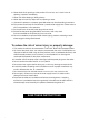
This product should be grounded. In the event of an electrical short circuit, grounding reduces the risk
of electric shock by providing an escape wire for the electric current. This product is equipped with a
cord having a grounding wire with a grounding plug. The plug must be plugged into an outlet that is
properly installed and grounded.
DANGER– Improper use of the grounding plug can result in a risk of electric shock.
If repair or replacement of the cord or plug is necessary, do not connect the grounding wire to either
at blade terminal. The wire with insulation having an outer surface that is green with or without yellow
stripes is the grounding wire.
Check with a qualified electrician or serviceman if the grounding instructions are not completely
understood, or if in doubt as to whether the product is properly grounded.
This product is for use on a nominal 120 V circuit, and has a grounding plug that looks like the plug
illustrated in sketch A. A temporary adapter, which looks like the adapter illustrated in sketches B and
C, may be used to connect this plug to a 2-pole receptacle as shown in sketch B if a properly grounded
outlet is not available. The temporary adapter should be used only until a properly grounded outlet
(sketch A) can be installed by a qualied electrician. The green colored rigid ear, lug, and the like
extending from the adapter must be connected to a permanent ground such as a properly grounded
outlet box cover. Whenever the adapter is used, it must be held in place by the screw.
If it is necessary to use an extension cord,
use only a three wire extension cord that
has a three-blade grounding plug, and
a three-slot receptacle that will accept
the plug on the product. Replace or
repair a damaged cord.
GROUNDING
METHODS
A B C
GROUNDED
OUTLET
BOX
METAL
SCREW
TAB FOR
METAL SCREW
ADAPTER
GROUNDED
OUTLET
GROUNDING PIN