
Installation Guide


M965735 Rev. 1.1 (7/16)
If sink does not hold water even though Stopper is in the “down” position:
• Follow CABLE ADJUSTMENT PROCEDURE.
If Stopper does not raise up fully or sink drains too slowly:
• Follow CABLE ADJUSTMENT PROCEDURE.
If you need to remove the Stopper:
• Follow STOPPER REMOVAL PROCEDURE.
If you would like the ability to remove your Stopper simply by lifting it out of the drain:
• Follow STOPPER INSTALLATION PROCEDURE for “Unlocked” mode.
Speed Connect
®
Drain
Troubleshooting Guide
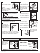
• Disconnect the Cable from the Drain by threading the Cable Connector (1) counter-clockwise. Fig. A.
• Look at the area on the Drain Body where the Cable was attached and locate the component labeled as
“Cam” in the illustration. Fig. B.
• Use a small screwdriver to rotate the Cam in the clockwise direction as far as it will go. At this point the
Stopper should be in the UP position. Fig. B, C.
• Push DOWN on the Lift-Knob to make sure it is fully down. Fig. C.
• Re-attach the Cable to the Drain Body Connection (2) by threading the Cable Connector (1) clockwise onto the
Drain Body Connection (2) and hand-tighten. Fig. A.
CABLE ADJUSTMENT PROCEDURE
CAM
CAM CAP
Fig. B.Fig. A.
2
1
RE-ATTACH
DISCONNECT
STOPPER
Fig. C.
DOWN
3
Fig. F.
REMOVE
CAM
Fig. E.Fig. D.
REMOVE
CAM CAP
• Disconnect the Cable from the Drain by threading the Cable Connector (1) counter-clockwise. Fig. A.
• Look at the area on the Drain Body where the Cable was attached and locate the component labeled
as “Cam” and “Cam Cap” in the illustration. Fig. B.
• Use ngers or small screwdriver under either side of the Cam Cap to pry it out from the Drain. Fig. D.
• Remove the Cam by pulling it straight out while wiggling gently to loosen the Rubber Seal. Fig. E.
• The Stopper can now be removed by lifting it out of the Drain. Fig. F.
STOPPER REMOVAL PROCEDURE