Installation and Operation Thermostats Standard and Programmable Versions SAFETY WARNING Only qualified personnel should install and service the equipment. The installation, starting up, and servicing of heating, ventilating, and air-conditioning equipment can be hazardous and requires specific knowledge and training. Improperly installed, adjusted or altered equipment by an unqualified person could result in death or serious injury.
Copyright © 2012Trane. All rights reserved. This document and the information in it are the property ofTrane and may not be used or reproduced in whole or in part, without the written permission ofTrane.Trane reserves the right to revise this publication at any time and to make changes to its content without obligation to notify any person of such revision or change. Trademarks Trane and its logo are trademarks ofTrane in the United States and other countries.
Table of Contents Introduction . . . . . . . . . . . . . . . . . . . . . . . . . . . . . . . . . . . . . . . . . . . . . . . . . . . . . . . . . . . . 5 Product Features and Capabilities . . . . . . . . . . . . . . . . . . . . . . . . . . . . . . . . . . . . 6 Dimensions . . . . . . . . . . . . . . . . . . . . . . . . . . . . . . . . . . . . . . . . . . . . . . . . . . . . . . . 7 Pre-Installation . . . . . . . . . . . . . . . . . . . . . . . . . . . . . . . . . . . . . . . . . . . . . . . . . . . . . . .
Heat and Cool Cycling Rate . . . . . . . . . . . . . . . . . . . . . . . . . . . . . . . . . . . . . . . . . 41 Minimum Compressor Off Time . . . . . . . . . . . . . . . . . . . . . . . . . . . . . . . . . . . . 41 Configuration and Programming Retention . . . . . . . . . . . . . . . . . . . . . . . . . . . 42 Extended Fan-on Time (Heat or Cool) . . . . . . . . . . . . . . . . . . . . . . . . . . . . . . . . 42 Compressor and Auxiliary Heat Lockout . . . . . . . . . . . . . . . . . . . . . . . . . . . . .
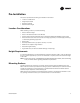
Introduction This document provides installation, operation, and troubleshooting information for threeTrane models of push-button thermostat: • TheTrane Programmable 3-Heat/2-CoolThermostat: – Trane PLM # X13511537-01 – Trane Clarksville part # BAYSTAT150A – Service parts #THT02774 • TheTrane (non-programmable) 3-Heat/2-CoolThermostat: – Trane PLM # X13511536-01 – Trane Clarksville part # BAYSTAT155A – Service parts #THT02773 • TheTrane (non-programmable) 1-Heat/1-CoolThermostat: – Trane PLM # X1351153
Introduction Product Features and Capabilities 1H/1C Thermostat (p/n X13511535-01) 3H/2C Thermostat (p/n X13511536-01) Programmable Thermostat (p/n X13511537-01) The table below shows the functional differences between the three thermostat models. A liquid crystal display (LCD) with symbols for temperature, setpoints, and system operating modes. The programmable thermostat also has day of the week, time of day, and occupancy settings. System modes: Heat, Cool, Auto, Off.
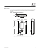
Introduction Dimensions Figure 1 and Figure 2 provide dimensions for each type of thermostat.The two non-programmable thermostats have the same dimensions; the programmable thermostat has slightly different dimensions. Figure 1. Programmable Thermostat Dimensions 0.3 in. (8 mm) 1.08 in. (27.5 mm) 3.25 in. (83 mm) Typ. Radius 0.08 in. (2 mm) 4.7 in. (119 mm) 3.4 in. (86 mm) Typ.P Radius 0.08 in. (2 mm) Note: Drawing not to scale. Dimensions within ± 0.02 in. (± 0.
Introduction Figure 2. 1-Heat/1-Cool or 3-Heat/2-Cool (non-programmable) Thermostat Dimensions 0.3 in. (8 mm) 1.1 in. (28 mm) 3.07 in. (78 mm) Typ. Radius 0.08 in. (2 mm) 4.7 in. (119 mm) 3.4 in. (86 mm) Typ.P Radius 0.08 in. (2 mm) Note: Drawing not to scale. Dimensions within ± 0.02 in. (± 0.
Pre-Installation This section provides the following pre-installation information: • Location considerations • Height requirements • Mounting surfaces • Maximum wire length Location Considerations When selecting a location, avoid the following: • Areas of direct sunlight • Areas in the direct airstream of air diffusers • Exterior walls and other walls that have a temperature differential between the two sides • Areas that are close to heat sources such as sunlight, appliances, concealed pipes
Pre-Installation Maximum Wire Lengths Thermostat to HVAC Equipment The thermostat may not function properly if the total resistance of any of the thermostat to HVAC equipment wires exceeds 2.5 ohms.To ensure that wire length does not cause excess resistance, refer to Table 1 and ensure that the wires from the thermostat to the HVAC equipment are not too long. Table 1. Maximum Thermostat to HVAC Equipment Wire Lengths Copper wire size Maximum recommended wire length 22 AWG (0.
Installation This section provides installation instructions. Before you begin, read through the pre-installation information, beginning on p. 9, and also verify the following conditions are met: • A wire access hole is available at the thermostat location. • The wires are accessible through the hole. • The wires are attached to the appropriate terminals on the HVAC equipment. • There is continuity (and not more than 2.5 ohms resistance) between the thermostat location and the HVAC equipment.
Installation Figure 4. Feeding Wires through Back Plate 4. If you are mounting the back plate directly to a wall surface, hold the back plate against the surface and mark the fastener locations. 5. Secure the back plate using appropriate fasteners. (See “Mounting Surfaces,” p. 9.)The thermostat must be level and plumb for accurate temperature control and to ensure proper air movement through the thermostat enclosure.
Installation 2. Align the pins on the circuit board with the holes on the bottom of the terminal blocks and gently push the wired terminal blocks into place on the circuit board. See Figure 5. Figure 5.
Installation Wiring Diagrams The following diagrams show all of the common wiring scenarios you are likely to encounter. 1-Heat/1-Cool Thermostat Use Table 3 and the diagrams that follow to correctly wire the thermostat for your system type. Table 3.
Installation Figure 8. 1H/1C Thermostat, 1H Only, Conventional Without Fan (Option 2) Rc L1 (hot) L2 R 24 Vac (jumper installed) Y C W Heat G Figure 9. 1H/1C Thermostat, 1H Only, Conventional With Fan (option 3) (jumper installed) Rc L1 (hot) L2 R 24 Vac Y C W Heat Fan G Figure 10.
Installation Figure 11. 3H/2C Non-Programmable Thermostat, 1H/1C, Conventional (Option 0) Single Transformer: (jumper installed) Rc L1 (hot) L2 R 24 Vac Compressor Y C Heat W G Fan W2 Y2 L Two Transformers: Cooling Transformer L1 (hot) L2 Rc R 24 Vac Compressor (jumper removed) Y C W Heat Fan Heating Transformer L1 (hot) L2 G W2 Y2 24 Vac L Figure 12.
Installation Figure 14. 3H/2C Non-Programmable Thermostat, 1H, Conventional With Fan (Option 3) Rc L1 (hot) L2 R 24 Vac (jumper installed) Y C Heat W G Fan W2 Y2 L Figure 15. 3H/2C Non-Programmable Thermostat, 1C, Conventional (Option 4) Rc L1 (hot) L2 R 24 Vac Compressor (jumper installed) Y C W Fan G W2 Y2 L Figure 16.
Installation Figure 17. 3H/2C Non-Programmable Thermostat, 2H/1C, Conventional (Option 6) Single Transformer: (jumper installed) Rc L1 (hot) L2 R 24 Vac Compressor Y C Heat 1 W G Fan W2 Heat 2 Y2 L Two Transformers: Cooling Transformer L1 (hot) L2 Rc R 24 Vac Compressor (jumper removed) Y C W Heat 1 Heating Transformer L1 (hot) L2 Fan Heat 2 G W2 Y2 24 Vac L Figure 18.
Installation Figure 20. 3H/2C Non-Programmable Thermostat, 3H/2C, Heat Pump With Auxiliary Heat (Option 9) L1 (hot) L2 Rc 24 Vac R (jumper installed) Y Compressor 1 C Changeover Valve O/B G Fan Auxiliary Heat Aux/E Y2 Compressor 2 L Zoning Panels Programmable Thermostat Use Table 5 and the diagrams that follow to correctly wire the thermostat for your system type. Table 5.
Installation Figure 21. Programmable Thermostat, 1H/1C, Conventional (Option 1) Single Transformer: C G Fan Y Compressor Heat L2 L1 (hot) W Rc 24 Vac R (jumper installed) W2 Y2 Economizer/TOD A S1 Remote Temperature Sensor S2 Two Transformers: Cooling Transformer L2 L1 (hot) C 24 Vac G Fan Compressor Heating Transformer L2 L1 (hot) Heat Y W Rc 24 Vac R (jumper removed) W2 Y2 Economizer/TOD A Remote Temperature Sensor S1 S2 Figure 22.
Installation Figure 23. Programmable Thermostat, 1H Only, Conventional Without Fan (Option 3) C G Y Heat L2 L1 (hot) W Rc 24 Vac R (jumper installed) W2 Y2 Economizer/TOD A Remote Temperature Sensor S1 S2 Figure 24. Programmable Thermostat, 1H, Conventional With Fan (Option 4) C G Fan Y Heat L2 L1 (hot) W Rc 24 Vac R (jumper installed) W2 Y2 Economizer/TOD A Remote Temperature Sensor S1 S2 Figure 25.
Installation Figure 26. Programmable Thermostat, 2H/1C, Heat Pump With Auxiliary Heat (Option 6) C G Fan Compressor L2 L1 (hot) 24 Vac Changeover Valve Y O/B Rc R Auxiliary Heat (jumper installed) W1 Y2 Economizer/TOD A Remote Temperature Sensor S1 S2 Figure 27.
Installation Figure 28. Programmable Thermostat, 2H/1C, Conventional (Option 8) Single Transformer: C G Fan Y Compressor Heat 1 L2 L1 (hot) W Rc 24 Vac R Heat 2 (jumper installed) W2 Y2 Economizer/TOD A S1 Remote Temperature Sensor S2 Two Transformers: Cooling Transformer L2 L1 (hot) 24 Vac C G Fan Compressor Heating Transformer L2 L1 (hot) Heat 1 Y W Rc 24 Vac (jumper removed) R Heat 2 W2 Y2 Economizer/TOD A Remote Temperature Sensor S1 S2 Figure 29.
Installation Figure 30. Programmable Thermostat, 2H/2C, Heat Pump Without Auxiliary Heat (Option 10) C G Fan Compressor 1 L2 L1 (hot) 24 Vac Changeover Valve Y O/B Rc R (jumper installed) W1 Compressor 2 Economizer/TOD Y2 A Remote Temperature Sensor S1 S2 Figure 31.
Installation Applying Power Applying power to the thermostat will initiate a power up sequence. 1. The full screen appears for 1.5 seconds. 2. The firmware version appears for 1.5 seconds: • On the programmable thermostat, the firmware version shows in the HH:MM digits. • On the non-programmable thermostats, the digits are split between the top and bottom regions of the screen: the most significant digits are at the top. 3. Power up tests are performed.
Configuration NOTICE Adverse Control System Behavior! Improper configuration could cause unwanted, possibly adverse control system behavior. Be sure to configure the thermostat according to your system type. To change the installation configuration: 1. Apply electrical power to the thermostat. 2. See the appropriate table for your thermostat type to determine the configuration options you need: • Table 6, p. 27 for 3-Heat/2-Cool programmable thermostats • Table 7, p.
Configuration 5. Press , , or to scroll through the options, identified by their numbers, until you reach the option you want to change: scrolls to a lower-numbered option. or scrolls to a higher-numbered option. 6. Use or to change the value of the option: decreases the value. increases the value. 7. Repeat Step 5 and Step 6 until you have made all necessary changes.
Configuration Table 6. No. Installation Options for 3-Heat/2-Cool Programmable Thermostat (continued) Default Opts.
Configuration Table 6. No. BAS-SVX36C-EN Installation Options for 3-Heat/2-Cool Programmable Thermostat (continued) Name Default 0220 Heat pump compressor lockout point(5) 0 0221 Heat pump aux lockout point 0 0230 Temp occupied duration limit for TOV override 3 0231 Number of periods 2 0232 Period occupied/ unoccupied definitions 4 Opts. Descriptions 0 None 15 15° F (–9.5° C) 20 20° F (–6.5° C) 25 25° F (–4.0° C) 30 30° F (–1.0° C) 35 35° F (1.5° C) 40 40° F (4.5° C) 45 45° F (7.
Configuration Table 6. No. Installation Options for 3-Heat/2-Cool Programmable Thermostat (continued) Default Opts.
Configuration Table 7. Installation Options for 3-Heat/2-Cool Non-Programmable Thermostat No. Name 01 System type Default Opts.
Configuration Table 8. Installation Options for 1-Heat/1-Cool Non-Programmable Thermostat No. Name Default Opts.
Operation This section provides general descriptive and procedural information intended for typical daily operators of the thermostat. Icon Descriptions Figure 36 describes the icons visible on the front of the thermostat. Note: Except when the thermostat is powering up, when all of the icons are shown for 2 sec, only some of the icons will be visible at once. Figure 36. Thermostat Icons Large numeric display - Shows current temperature but can indicate other information. Temperature units - F or C.
Operation Non-Programmable Thermostats Non-programmable thermostats do not have timekeeping or scheduling capabilities.They will continue to maintain heating and/or cooling setpoints until an operator makes changes to the setup.Therefore, only the following tasks may be required performed: • Change the system mode. • Show or change the heating or cooling temperature setpoint. • Change the fan mode.
Operation Changing the Fan Mode Note: If you are unable to see the fan mode, check the system type setting in the installation configuration options to make sure that it is specified as a system with a fan. There are two fan modes. Each are indicated by an icon on the display: Auto mode turns the fan on and off as needed according to equipment configuration. On runs the fan continuously. To change the fan mode: 1. Press > 2. Press or > .The current mode flashes. to change the mode.
Operation Scheduling The thermostat can be configured for two periods (day and night) or four periods (morning, day, evening, and night).The chosen number of periods are applied to each day of the week when you program the thermostat. Each period can have a unique start time, heat setpoint, cool setpoint, and fan setting. The groups of days can be one of the following: • 1 day = all 7 days of the week follow the same schedule.
Operation Table 9. Weekly Operating Schedule Worksheet Day Four period default settings Period Monday Tuesday Wednesday Thursday Friday Saturday Sunday BAS-SVX36C-EN Heating setpoint Cooling setpoint Fan Setting Morning 6:00 am 70° F (21.0° C) 78° F (25.5° C) Auto Day 8:00 am 62° F (16.5° C) 85° F (29.5° C) Auto Evening 6:00 pm 70° F (21.0° C) 78° F (25.5° C) Auto 10:00 pm 62° F (16.5° C) 82° F (28.0° C) Auto 6:00 am 70° F (21.0° C) 78° F (25.
Operation To set the schedule: 1. Press > > > .The display shows only the following elements: Mo Tu We Th Fr Sa Su 2. Press . Note: At this point the thermostat is in schedule change mode. It returns to normal operating mode if no buttons are pressed for 45 sec.To manually exit schedule change mode, press and hold for 2 sec. Note: If flashes and you are unable to enter schedule change mode, the mode is locked. See “Locking or Unlocking Modes,” p. 40. 3.
Operation Day-to-Day Operation After a programmable thermostat is configured and the schedule is programmed, the thermostat automatically changes the setpoints and fan settings according to the schedule.However, there are some operator tasks that you may need or want to perform: • Show setpoint or current temperature.You can temporarily or permanently switch the main display from current temperature to temperature setpoint. See “Showing the Setpoint or Temperature on Display,” p. 39.
Operation Timed Override (TOV) Mode During normal operation, the thermostat controls the HVAC equipment according to the schedule that is programmed into it.To permanently change the temperature setpoint or fan setting, make the change in the programmed schedule (see “Scheduling,” p. 36). However, a timed override can be used to temporarily change the current settings without making any change to the schedule. To start a temperature setpoint override: 1. Press or .
Operational and Programming Reference Information This section provides additional information that may be useful for understanding thermostat operation or programming. Deadband The thermostat automatically maintains a temperature deadband between the heating setpoint and the cooling setpoint whenever automatic changeover (heat-to-cool or cool-to-heat mode) is enabled.The temperature range of the deadband is 2–9 °F (1.0–4.
Operational and Programming Reference Information Configuration and Programming Retention The thermostat retains the time and date for a minimum of 5 days with no electricity. If power is lost for more than 5 days, you will need to reset the time and date when power is restored. All configuration parameters, system settings, and scheduling are stored in non-volatile memory, which will retain the data indefinitely with or without power.
Troubleshooting This section describes troubleshooting for the thermostat. Error Codes An error code indicates that technical assistance may be required. Try cycling the power to the thermostat as a first method to clear the error. See Table 10 below and Table 12, p. 47 for additional information. Note: On the display, error codes appear at the bottom of the display. Note: On the programmable thermostat, the error code alternates with the time on the display. Table 10.
Troubleshooting WARNING Live Electrical Components! The circuit board is energized. Have a qualified licensed electrician or other individual who has been properly trained in handling live electrical components perform this step. Failure to follow all electrical safety precautions when exposed to live electrical components could result in death or serious injury. a. Remove the thermostat cover. b. Press and hold the configuration button for at least 3 sec, then release it. Figure 39.
Troubleshooting 5. Use or to change the value of the option: decreases the value. increases the value. 6. Repeat Step 4 and Step 5 until you have conducted all needed tests. 7. Change the value of the power up test (test number 8 for the 1-Heat/1-Cool thermostat; test number 11 for the 3-Heat/2-Cool or programmable thermostat) to 1 to run a power up test after you exit test mode. 8.
Troubleshooting Table 11. System Test Descriptions 3H/2C Thermostat (p/n X13511536-01) Programmable Thermostat 1H/1C Thermostat (p/n X13511535-01) Test Number 1(1) Description Values 1 1 Heating system 0 = all heating stages off 1 = heat stage 1 on; heat stage 2 off 2 = heat stage 2 on; heat stage 1 off 3 = heat stage 1 and 2 on This setting remains active when you scroll to the next setting.
Troubleshooting Troubleshooting Table Use Table 12 to diagnose and solve problems you may encounter. Table 12. Troubleshooting BAS-SVX36C-EN Problem Solution Error code E0 Thermistor error. • For non-programmable thermostats and programmable thermostats set to use internal temperature sensor (configuration option #210 set to 0, 1, or 2): Thermistor is defective or local temperature is out of range. Replace or repair thermostat through a qualified Trane supplier.
Thermostat Specifications Table 13. Specifications Programmable Thermostat Non-Programmable Thermostats Input power 24Vac, 50Hz or 60Hz (18Vac to 32Vac) (Power supply frequency selected using installation configuration option #190) 24Vac, 50Hz or 60Hz (18Vac to 32Vac) (Power supply frequency selected using installation configuration option #11) Wire size 18 to 22 AWG 18 to 22 AWG Output terminal ratings 1A @ 30Vac 1A@ 30Vac Indoor temperature display range +15 to +122°F (–9.