
Installation Guide

4
710443-100 Rev. A 8/18
This unit is best installed by two people.
Cover drain with tape prior to installation to prevent the loss of small parts.
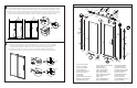
Unpack your unit carefully and inspect for freight damage. Lay out and identify all parts using Box Contents and
Assembly Drawing as a reference. Before discarding the carton check to see that no small hardware parts have fallen
to the bottom of the box. If any parts are damaged or missing refer to the description noted in the instructions when
inquiring about replacements.
Handle the glass panels carefully and protect the edges. Although tempered glass is very resistant to breakage the
glass can still break if unequal pressure is applied during installation and the sharp corners of the panel can damage
tile and ooring surface.
Be sure to wear safety glasses whenever drilling or cutting. When drilling holes in ceramic tile or marble use a center
punch and hammer to carefully break the glazed surface. This will prevent skidding when drilling.
NOTE: TEMPERED GLASS CANNOT BE DRILLED, CUT OR MODIFIED.
1
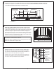
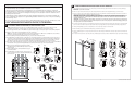
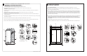
INSTALLATION NOTES:
NOTE: The illustrations below show the door assembled with the handle on the right side of shower. If the door is to be
assembled so the handle is on the left side, the door panels and procedure need to be reversed in those areas.
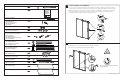
1a. Determine approximate location of Fixed Wall Post [22] from threshold edge of shower pan approx. 15/16" (23mm) and plumb.
1b. Mark top 2 hole locations in the Fixed Wall Post [22] onto shower wall.
NOTE: The 2 top holes in the Fixed Wall Post [22] are used for marking where to drill holes as a template for Connector Base
Mounts [12] on both left and right sides of shower, not for mounting screws.
1c. Drill a 1/4" (6mm) pilot hole (if using Wall Anchors [14] ) at each of the 2 marked locations.
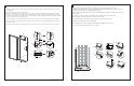
1d. Insert Wall Anchors [14] into pilot holes of wall. Remove Connector Base Mounts [12 a & b] from Wall Connectors [11], place a
clear plastic Cushion [13] between the Base Mount and shower wall keeping the nished, chrome plated edge of Base facing
inside shower and screw into place using 2 M5x35 Flathead Screws [15]. Repeat procedure (1a-1d) for mounting Connector
Base Mount on opposite side of shower, keeping the nished chrome plated edge of base facing outside of shower.
1e. Once both Connector Base Mounts [12 a & b) are secured to the wall, place Fixed Wall Post [22] on side of shower that will hold
the Fixed Glass Panel [31] and mark approximately 3/16" (5mm) from threshold edge of shower pan and plumb.
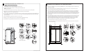
1f. Mark 3 holes along the length not previously used in the
Fixed Wall Post [22] pre-drilled with slight oval (Ref. 1b) onto
the shower wall.
1g. Drill 1/4" (6mm) pilot hole (if using Wall Anchors [14] ) at
each marked location.
1h. Insert Wall Anchors [14] into pilot holes. Place Fixed Post
[22] into position and secure to wall using 3 M4x35mm [23]
pan head screws.
ATTACHING CONNECTOR BASE MOUNTS AND FIXED WALL POST
[22]
[22]
[23]
[24]
5 mm
1e
1f
1g
1h
[12]
[15]
[13]
[14]
1a
1b
1b
1c
1d
[22]
[22]
[22]
[22]
[22]
[22]
15/16"
23 mm
9
710443-100FR Rev. A 8/18
6
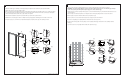
FIXER LE PANNEAU DE PORTE COULISSANT AU RAIL HORIZONTAL
1a. Placer minutieusement le panneau de porte coulissant [32] sur le rail horizontal [1] depuis l’intérieur de la douche et sur les cylindres [8].
REMARQUE: 2 personnes nécessaires.
1b. Veiller à ce que le bas du panneau de porte coulissant [32] entre dans la rainure ouverte du guide inférieur [6] et soit mis en place.
1c. Retirer le capuchon de protection leté du protège-panneau de porte [10] (extrémité en plastique transparent) et retirer la vis de rétention à
l’intérieur à l’aide du tournevis cruciforme et séparer les deux pièces.
REMARQUE: Ne pas perdre l’écarteur en plastique entre ces deux pièces! Avec les deux rondelles en plastique transparent
fournies, placer une rondelle sur une extrémité du protège-panneau et une rondelle sur l’autre extrémité, et les faire passer dans le
trou du panneau de porte coulissant [32] avec l’extrémité la plus épaisse orientée vers l’extérieur de la douche. Remettre la vis
cruciforme en place et serrer.
REMARQUE: Si la vis ne rentre plus dans le letage, les deux pièces sont clavetées et il peut être nécessaire de les faire tourner à
180degrés. Les protège-panneaux de porte peuvent être ajustés de sorte à être le plus proches du rail horizontal [1] possible pour
éviter que la porte ne sorte du rail horizontal.
1d. Il peut être nécessaire de placer une clé hexagonale sur l’un des trous du protège-panneau pour faire office de poignée ou de levier pendant
que vous serrez la vis. Placer le capuchon de protection leté sur le protège-panneau de porte. Reproduire pour l’autre protège-panneau.
1e. Fixer le joint magnétique [19] sur le côté du panneau où se trouve la poignée de la porte et l’enclencher.
1f. Fixer le montant [20] sur le montant mural coulissant [21] et l’enclencher en place.
1g Fixer le joint latéral [16] sur le côté opposé du panneau de porte coulissant [32] en maintenant le côté le plus large orienté vers l’extérieur de
la douche.
1h & 1i Il peut être nécessaire de couper une portion du joint latéral [16] vers le haut pour laisser suffisamment d’espace pour le rail horizontal [1].
[8]
[19]
[20]
[21]
[16]
[1]
[10]
1a 1b
1e
1c
1d
1f
1g
1h
1i
[8]
[6]
[32]
[19]
[10]
[16]
[20]
[21]
[10]