
Installation Guide


- 2 -
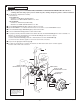
NOTE: When soldering, remove PLASTER GUARD, CARTRIDGE and PRESSURE BALANCING UNIT. When finished
soldering, flush valve body, replace pressure balanceing unit, cartridge and plaster guard to continue installation.
n See Roughing-in diagram before starting.
Connections are:
• R117 & R117SS
— INLETS 1/2" PEX INLETS (ASTM F1807-2)
— OUTLETS 1/2" NOM. COPPER SWEAT or 1/2" NPT
• R118 & R118SS
— INLETS 1/2" PEX INLETS (ASTM F1960)
— OUTLETS 1/2" NOM. COPPER SWEAT or 1/2" NPT
n Secure MOUNTING BRACKET (8) to wall brace with wood screws.
n Mount VALVE BODY to cross brace with-in wall. Use wood screws to secure VALVE BODY to brace.
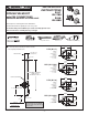
n Connect RISER PIPE (1) to MANIFOLD (2) top outlet marked “SHR”.
n Connect TUB FILLER PIPE (3) at bottom outlet marked “TUB”.
n For proper positioning the nished wall must be within side wall of PLASTER GUARD (4). If the valve is installed on a
berglass or other thin wall application, the PLASTER GUARD (4) can be used as a support.
• Cut a 3" dia. hole in the shower stall.
• Remove PLASTER GUARD (4), rotate 90˚ so that indicated screw holes t MANIFOLD (2).
• Connect hot and cold water supplies. Connections are1/2" PEX connections.
n Cap off shower pipe (5) and tub ller pipe (6).
n For support, use pipe braces secured to wooden braces. With valve turned off, turn on water supplies.
Check for leaks. Finish wall construction.
ROUGHING-IN
1
M968931 Rev. 1.6 (7/15)
CAUTION
Turn off hot and cold water
supplies before beginning.
COLD
HOT
1
2
5
8
3
6
4
1/2" PEX
CONNECTION
(ASTM F1807)
WOOD SCREWS
CROSS BRACE
Attention: Do not connect
PEX adapters to tub outlet as
this can cause reduction in
flow and back flow to shower
while in tub mode.
R118
R117
OUTLET 1/2" NOM.
COPPER SWEAT or 1/2" NPT
OUTLET 1/2" NOM.
COPPER SWEAT or 1/2" NPT
1/2" PEX INLETS
(ASTM F1960)