
Installation Guide


- 3 -
M965660 Rev. 1.0 (7/15)
PRY RED RING FORWARD AND ROTATE
COUNTER-CLOCKWISE ONE CLICK
PRY RED RING FORWARD AND ROTATE CLOCKWISE
"A"
ADJUSTMENT WHEN WATER IS TOO HOT
"A"
"B"
"B"
ADJUSTMENT WHEN WATER IS TOO COLD
"RED RING"- HOT LIMIT SAFETY STOP
TEMPERATURE SETTING NUMBERS
0
1
2
3
4
5
6
1
N⁄MEROS DE AJUSTE DE TEMPERATURA
ìANILLO ROJOî - LIMITADOR DE SEGURIDAD DE AGUA CALIENTE
« ANNEAU ROUGE » - DISPOSITIF DE SÉCURITÉ ANTI-BRÛLURE
LEVANTE EL ANILLO HACIENDO PALANCA Y GIRE HACIA
LA DERECHA
AJUSTE CUANDO EL AGUA ESTÁ DEMASIADO FRÍA
LEVANTE EL ANILLO HACIENDO PALANCA
Y GIRE UN CLIC HACIA LA IZQUIERDA
AJUSTE CUANDO EL AGUA ESTÁ DEMASIADO CALIENTE
NOMBRES DE RÉGLAGE DE LA TEMPÉRATURE
SOULEVER L’ANNEAU ROUGE VERS L’AVANT ET
TOURNER D’UN CRAN DANS LE SENS
CONTRAIRE DES AIGUILLES D’UNE MONTRE.
RÉGLAGE LORSQUE LA TEMPÉRATURE DE
L’EAU EST TROP ÉLEVÉE
SOULEVER L’ANNEAU ROUGE VERS
L’AVANT ET TOURNER DANS LE SENS
DES AIGUILLES D’UNE MONTRE
RÉGLAGE LORSQUE LA TEMPÉRATURE
DE L’EAU EST TROP BASSE
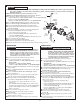
n Remove CARTRIDGE (1) by removing CARTRIDGE SCREWS (2). Remove three SCREWS (3) from FIXATION RING (4)
and pull out PRESSURE BALANCING (5) unit.
n Clean SEALS (9) on base of CARTRIDGE (1). Check base of PRESSURE BALANCING UNIT (5) and clean O-RINGS (6). Remove CAPS (7) and
check O-RINGS on inside of CAPS (7). Clean inside sealing surfaces of VALVE BODY (8).
n Re-assemble PRESSURE BALANCING UNIT (5) and CARTRIDGE (1). Tighten all screws
UNABLE TO MAINTAIN CONSTANT TEMPERATURE
n Remove PRESSURE BALANCE UNIT (5).
n Remove CAPS (7) and clean valve thoroughly.
n Examine balancing unit and check condition of O-ring on end of piston. Piston should move back and forth. Order Repair Part M952100 if
balancing unit is defective.
n Replace CAPS (7) and install PRESSURE BALANCE UNIT (5). Make sure inlets line up with two holes in bottom of casting. Top ange should
butt-up against top of casting.
UNABLE TO MAINTAIN CONSTANT TEMPERATURE
n Remove PRESSURE BALANCE UNIT (5). Rotate PRESSURE BALANCE UNIT (5) 180˚ so that the inlets face up and the large outlet
port faces down.
n Push PRESSURE BALANCE UNIT (5) in casting making sure inlets line up with holes in bottom of casting. Top ange should butt up against
top of casting.
n Reassemble FIXATION RING (4) and CARTRIDGE (1).
2
3
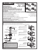
ADJUST HOT LIMIT STOP
REGULE EL LIMITADOR DE AGUA CALIENTE
RÉGLAGE DE LA BUTÉE DE LIMITATION DE CHAUD
By restricting handle rotation and limiting the amount of hot water allowed to mix with
the cold, the HOT LIMIT SAFETY STOP (1) reduces risk of accidental scalding. To set
the maximum hot water temperature of your faucets, all you need to do is adjust
the setting on the HOT LIMIT SAFETY STOP (1).
n Turn CARTRIDGE STEM (2) to the OFF position (coldest setting) before making
adjustment to HOT LIMIT STOP (1). Use a at blade screwdriver to pry free the
HOT LIMIT SAFETY STOP (1). Pull forward and rotate counterclockwise one
number to limit hot water temperature. Use ARROW (3) on CARTRIDGE (4) and
NUMBERS (5) on HOT LIMIT STOP (1) for indication.
El LIMITADOR DE SEGURIDAD DE AGUA CALIENTE restringe la rotación de la manija
y limita la cantidad de agua caliente que puede mezclarse con el agua fría, con el fin de
evitar el riesgo de quemaduras accidentales. Para definir la temperatura máxima del
agua caliente de los grifos, sólo debe ajustar el LIMITADOR DE SEGURIDAD DE AGUA
CALIENTE.
n Gire el TALLO DEL CARTUCHO (2) a la posición de cierre (OFF, la más fría) antes de
efectuar los ajustes al LIMITADOR DE AGUA CALIENTE (1). Utilice un destornillador
plano para separar el LIMITADOR DE AGUA CALIENTE (1). Tire hacia fuera y gire en
sentido antihorario una posición para limitar la temperatura del agua caliente. Use la
FLECHA (3) del CARTUCHO (4) y los NÚMEROS (5) del LIMITADOR DE AGUA
CALIENTE (1) como indicadores.
En limitant la rotation de la poignée et en contrôlant la quantité d’eau chaude qui se mélange à l’eau froide, la BUTÉE DU LIMITEUR D’EAU
CHAUDE réduit les risques de brûlure accidentelle. Pour régler la température maximale de l’eau chaude dispensée par le robinet, ajuster le
réglage de la BUTÉE DU LIMITEUR D’EAU CHAUDE
n Amener la TIGE DE CARTOUCHE (2) à la position OFF (réglage le plus froid) avant d’entreprendre le réglage de la BUTÉE DE LIMITATION
DE CHAUD (1). Utiliser un tournevis plat pour dégager la BUTÉE DE SÉCURITÉ DE LIMITATION DE CHAUD (1). Tirer vers l’avant et tourner
d’un nombre dans le sens contraire des aiguilles d’une montre pour limiter la température de l’eau chaude. Utiliser la FLÈCHE (3)
sur la CARTOUCHE (4) et les NOMBRES (5) sur la BUTÉE DE LIMITATION DE CHAUD (1) pour se repérer.
1
5
1
3
1
1
9
7
5
3
1
0
1
5
1
3
1
1
9
7
5
3
1
1
5
1
3
1
1
9
7
5
3
1
COLDER
(Larger Numbers)
MÁS FRÍA
(números mayores)
PLUS FROID
(Nombres plus grands)
0 1 3 5 7 9 11 13 15
HOTTER
(Smaller Numbers)
MÁS CALIENTE
(números menores)
PLUS CHAUD
(Nombres plus petits)
0 1 3 5 7 9 11 13 15
1
5
1
5
4
4
3
3
2
2
VALVE LEAKS WHEN SHUT OFF