
Installation Guide


- 2 -
M965925 (5/18)
• Note: Refer to Roughing-in Dimensions on page 1 for additional information.
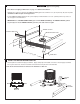
• Adequate floor support is required. The WOOD SUPPORT (1) must be a minimum of 2" (51 mm) thick by 10" (254 mm) wide.
2x6 lumber is NOT adequate for this application.
• Locate WOOD SUPPORT (1) between floor joists keeping a minimum distance of 2-3/4" (70 mm) from the top surface of
wood support to the finished floor.
• IMPORTANT: Use a ROUND BUBBLE LEVEL (2) to level the WOOD SUPPORT (1). The WOOD SUPPORT (1) must
be perfectly level. Secure WOOD SUPPORT (1) to floor joists. Check for level again.
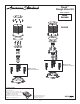
• Sweat together Hot and Cold Supply assemblies. Apply sealing tape to threaded connections. Thread supply assemblies
into rough-in valve inlets. The Hot inlet will be on the left when facing the front of the Tub Filler.
Note: The Hot and Cold inlets are marked on the maniflod. See View “A”.
1
INSTALL HOT AND COLD WATER SUPPLIES
INSTALL TUB FILLER FLOOR SUPPORT
2
FRONT
Turn off hot and cold water
supplies before beginning.
CAUTION
FINISHED FLOOR LINE
2-3/4" (70mm) MIN.
FLOOR JOIST
2 ROUND BUBBLE LEVEL
1 WOOD SUPPORT
10" (254mm) MIN.
2" (51mm) MIN.
10"-12" (254-305mm)
HOT
COLD
SEALING
TAPE
SUPPLY
ASSEMBLY
FRONT
HOT
COLD
View “A”