
Installation Guide


- 3 -
M965925 (5/18)
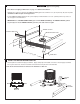
*Important: FRONT of ROUGH-IN VALVE (1) must face bath rim. Figure 1.
1
2
HOT
COLD
Fig. 2
FRONT
HOT
COLD
FINISH PLUMBING CONNECTIONS
LEVEL ROUGH-IN VALVE
4
• Locate the position on the wood support where the ROUGH-IN VALVE (1) will be installed.
Use the ROUGH-IN VALVE (1) as a guide to mark the four mounting hole locations. Fig. 1.
• Remove ROUGH-IN VALVE (1) and drill four pilot holes of 3/8" (9 mm) in diameter. Fig 2.
• Install the 4 MOUNTING SCREWS (2) into wood support.
• Install ROUGH-IN VALVE (1) onto the 4 MOUNTING SCREWS (2) and tighten NUTS &
WASHERS (2) supplied.
• Complete all Hot and Cold supply connections.
• Turn on water supplies and ckeck for leaks.
INSTALL ROUGH-IN VALVE
3
1
1
FRONT
Fig. 1
HOT
COLD
*FRONT
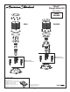
• Check that top of the ROUGH-IN VALVE (1) is level in all directions. If the ROUGH-IN VALVE (1)
is not level follow the steps below.
1. Loosen the four MOUNTING NUTS (2).
2. Adjust the LEVELING NUTS (2a) until the TUB FILLER is level in all directions.
3. Tighten the four MOUNTING NUTS (2) and check that theTUB FILLER is still level. If adjustment is still required loosen
MOUNTING NUTS (2) and adjust LEVELING NUTS (2a).
• Verify that the ROUGH-IN VALVE (1) is level and then fully tighten
NUTS & WEASHERS (2).
2
2a
LEVELING NUT
FLAT WASHER
LOCK WASHER
MOUNTING NUT
MOUNTING SCREW
NOTE: IF INSTALLING ON A CONCRETE SLAB
• Drill four pilot holes of 12.5 mm (1/2") in diameter.
• Insert a concrete anchor in each pilot hole.
• Install the 4 MOUNTING SCREWS (2) into the 4 concrete anchors.
Tighten NUTS & WASHERS (2) supplied.
*
Concrete anchor not included. But available commercially.
Concrete Anchor
S12 (12mm)