
Installation Guide

- 2 -
M965907 Rev. 1.2 (8/19)
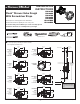
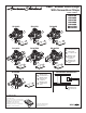
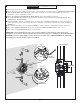
STANDARD WALL INSTALLATION
1
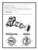
CAUTION
Turn off hot and cold water
supplies before beginning.
COLD
1
2
3
WOOD
SCREWS
CROSS BRACE
HOT
6
8
SERVICE
STOPS
4"
(101 mm)
2 x 4
Cross
Brace
7/8" TO 2"
(22 mm to
50 mm)
3-1/2"
(100 mm)
2-3/4" MAX.
(69 mm)
1-3/4" MIN.
(45 mm)
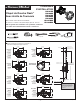
SIDE VIEW
NOTE: TO AVOID SHOWER RISE OR
OTHER RELATED ISSUES, DO NOT
USE PEX CONNECTIONS AT THE TUB
OUTLET CONNECTING TO THE TUB
SPOUT.
n See Roughing-in diagram before starting.
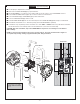
n Remove the PLASTER GUARD (8) for proper installation.
n Mount VALVE BODY to cross brace (2" X 4") with-in wall. Use wood screws to secure VALVE BODY to brace.
n Connect HOT and COLD water supplies per connection method of selected valve.
n Connect RISER PIPE (1) to VALVE BODY (2) top outlet marked “UP”.
n Connect TUB FILLER PIPE (3) to bottom outlet.
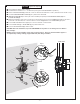
n Install PLASTER GUARD (8) back onto the valve. Only remove PLASTER GUARD (8) when ready to install trim Kit.
n Finished wall should allow for a 4" diameter opening (Use PLASTER GUARD for guidance)
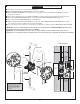
n Screw driver stops are primarly used to shut water off. To shut “HOT” or “COLD” water using a at head screw driver,
turn the head of the screw vertically. And to turn the water back on, turn the screw horizontally.
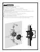
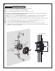
CAUTION: After valve installation, inspect the VALVE BODY for any debris. It can damage Pressure Balance
Valve cartridge.
NOTE: For back to back installation, follow steps mentioned above. Reversal of Hot/Cold water supplies is
accomplished by rotating cartridge (supplied with trim) 180° during installation.