
Installation Guide


M965613 REV. 1.8 (11/16)
5
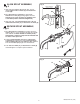
INSTALL SUPPLY ELBOW
ASSEMBLY & CONTROL BOX;
Fig. 7 and Fig. 7a
1. Install HOSE CLAMP (22) onto SPOUT HOSE (15).
Install SPOUT HOSE (15) onto ELBOW NIPPLE (23).
Fully tighten HOSE CLAMP (22) to secure SPOUT
HOSE (15) to ELBOW ASSEMBLY (24). Fig. 7.
2. Using the ANCHORS (25) and SCREWS (26) supplied,
attach ELBOW ASSEMBLY (24) to finished wall, covering
the hole in wall. Fig. 7.
3. Remove CONTROL BOX COVER (27). Feed
EXTENSION CABLES (5b) THROUGH GROMMET (28)
in back of CONTROL BOX (29). (Refer to VIEW “A”). Hold
the CONTROL BOX (29) so that it covers the wall opening
and mark the four mounting hole locations as shown. Fig.
7a.
4. It is recommended that the CONTROL BOX (29) be
secured to a wall stud or cross brace within the wall using
the SCREWS (30) supplied. If the CONTROL BOX (29) is
to be installed on tile or plaster walls, the ANCHORS (31)
and SCREWS (30) should be used.
2
22
25
26
27
29
31
30
28
24
15
23
Fig. 7
Fig. 7a
5b
VIEW “A”
VIEW “A”
32
35
33
34
24
29
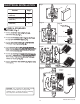
Fig. 8
LAVATORY RIM OR
MOUNTING SURFACE
NOTE: If using Mixing Valve (optional) See Sheet
#M968808 for installation instructions.
CONNECT SPOUT HOSE TO
CONTROL BOX; Fig. 8
3
1. Connect G 1/2˝ end of SUPPLY HOSE (32) to the
ELBOW ASSEMBLY (24). Tighten with adjustable
wrench to make a water tight connection.
2. Connect G 3/8˝ end of SUPPLY HOSE (32) to nipple
on top of CONTROL BOX (29). Tighten with adjustable
wrench to make a water tight connection.
3. IMPORTANT: INSERT FIBER WASHER (33)
INTO SUPPLY NUT (34) ON CONTROL BOX (29).
4. Connect FLEXIBLE SUPPLY (35) to bottom SUPPLY
NUT (34). Connect other end directly to wall supply.
Connection is G 3/8" compression.
Note: FLEXIBLE SUPPLY (35) measures 20" from the
bottom of the CONTROL BOX (29) base. If additional
supply length is required, installer must purchase parts
separately. If FLEXIBLE SUPPLY (35) is too long, loop to
avoid kinking.
COLD WATER OR
TEMPERED
WALL SUPPLY
CONTROL BOX
FOR HARDWIRE
INSTALLATION
(supplied by others)
9" TO 12"
(229mm TO 305mm)
NOTE: Find plastic bag containing 4 M5X16 screws
to be used for securing the CONTROL BOX COVER (1)
when installation is complete.