
Installation Guide
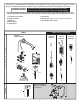


INSTALL SPOUT MOUNTING KIT;
Fig. 2
1a
M965613 REV. 1.8 (11/16)
Fig. 2
Fig. 3
Fig. 4
1. Make sure that SEAL (7) is installed into the groove
on the back of the MOUNTING FLANGE (8). Feed
the CORD HOLDER (3a) and the EXTENSION
CABLES (5a) through the MOUNTING FLANGE (8).
2. Install the MOUNTING FLANGE (8) to the wall with
three SCREWS (9) that thread into the MOUNTING
PLATE (10) within the wall. DO NOT fully tighten
the SCREWS (9). HAND TIGHTEN ONLY.
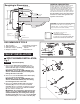
1. Slide SPOUT ESCUTCHEON (11) onto SPOUT (12).
2. Slide COMPRESSION RING (13) and
COMPRESSION SEAL (14) onto SPOUT (12).
3. Connect SPOUT HOSE (15) onto CORD HOLDER (3a)
by pressing until secure connection is achieved .
INSTALL SPOUT ASSEMBLY;
Fig. 3
1b
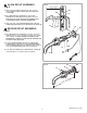
1. Connect the FAUCET SENSOR CONNECTORS (16)
to the EXTENSION CABLES (5a), and secure the
connections by installing into CONNECTOR HOUSINGS
(17) as shown. Rotate the END CAPS (18) to secure the
connection within the CONNECTOR HOUSINGS (17).
2. Pull the bottom end of EXTENSION CABLES (5b)
so that the CONNECTOR HOUSINGS (17) are inside
the wall.
4. Pull bottom CORD HOLDER (3b) and fish SPOUT
HOSE (15) through the wall and out through the
bottom wall opening (19).
5. Cut the CORD HOLDER (3a) off the end of the
SPOUT HOSE (15) as shown.
IMPORTANT: Secure the SPOUT HOSE (15) from
falling back through the wall opening (19).
SECURE WIRE CONNECTIONS;
Fig. 4
1c
3
7
10
8
3a
9
5a
3b
3a
15
17
16
19
17
18
18
5a
5b
11
15
3a
13
14
12
CUT SPOUT
HOSE