
Installation Sheet


1
31
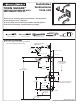
INSTALL TRIM
CAUTION: Protect finish on SHOWER ARM,
SHOWER HEAD and TUB SPOUT when installing.
2
A
6
7
7A
3
1
4
9
5
5
8
HEX WRENCH
When finished tiling the wall, remove PLASTER GUARD (A)
and turn off water supply.
Push CAP (1) over VALVE CARTRIDGE (2).
Mount ESCUTCHEON (3) to valve body with SCREWS (4).
OPTIONAL: Push DECORATIVE SCREW COVER (9)
(purchased separately) onto CAP (1) flush against ESCUTCHEON (3).
Remove PIPE CAPS (5) from shower pipe and tub filler pipe.
Install SHOWER ARM (6), SHOWER HEAD (7 or 7A) by
threading onto pipe nipple using teflon tape or pipe sealant.
Install SLIP-ON TUB SPOUT (8). Tighten with
HEX WRENCH supplied.
1-3/4" REF.
3
M965112 REV.1.4 (8/15)
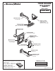
Align and install HANDLE (1) onto valve stem.
Tighten SET SCREW (2) using 2.5mm Hex
Wrench supplied. Push in index (4).
Check proper operation of HANDLE (1).
Turn on water supply on and test installed fitting.
Operate valve and DIVERTER SPOUT (3).
HEX WRENCH
2
4
VALVE STEM
"B"
"B"
2
ADJUST HOT LIMIT STOP
By restricting handle rotation and limiting the amount
of hot water allowed to mix with the cold, the HOT
LIMIT SAFETY STOP reduces risk of accidental scalding.
To set the maximum hot water temperature of your
faucets, all you need to do is adjust
the setting on the HOT LIMIT SAFETY STOP.
Use a flat blade screwdriver or your fingers
to pull up and rotate red HOT LIMIT SAFETY
STOP (1). Follow Step "A" or "B" to adjust
min./max. discharge temperature. "0" being
the hottest to "7" the coldest temperature
setting. Factory set at "0".
HOT LIMIT SAFETY STOP ADJUSTMENT
PRY RED RING
FORWARD AND ROTATE
COUNTER-CLOCKWISE
ONE CLICK
PRY RED RING
FORWARD AND
ROTATE CLOCKWISE
"A"
"A"
ADJUSTMENT WHEN
WATER IS TOO HOT
ADJUSTMENT WHEN
WATER IS TOO COLD
"RED RING"- HOT
LIMIT SAFETY STOP
TEMPERATURE
SETTING
NUMBERS
1
0
1
2
3
4
5
6
INSTALL HANDLE and TEST FITTING