
Installation Sheet


7
8
4
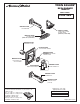
Remove CARTRIDGE (7) by removing CARTRIDGE
SCREWS (8). Remove three SCREWS (9) from
FIXATION RING (10) and pull out PRESSURE
BALANCING (16) unit.
Clean SEALS (11) on base of CARTRIDGE (7).
Check base of PRESSURE BALANCING UNIT (12)
and clean O-RINGS (13). Remove CAPS (14)
and check O-RINGS on inside of CAPS (14) for
debris. Clean inside sealing surfaces of VALVE
BODY (15). Re-assemble PRESSURE BALANCING
UNIT (12) and CARTRIDGE (7). Tighten
all screws.
VALVE LEAKS WHEN SHUT OFF
5
DO: SIMPLY RINSE THE PRODUCT CLEAN WITH CLEAR WATER. DRY WITH A SOFT COTTON FLANNEL CLOTH.
DO NOT: DO NOT CLEAN THE PRODUCT WITH SOAPS, ACID, POLISH, ABRASIVES, HARSH CLEANERS, OR A
CLOTH WITH A COARSE SURFACE.
CARE INSTRUCTIONS:
M965112 REV.1.4 (8/15)
SERVICE
CARTRIDGE
INLETS
7
6
HEX WRENCH
3
1
4
5
2
Remove PRESSURE BALANCE UNIT (12).
Remove CAPS (14) and clean valve thoroughly.
Examine balancing unit and check condition of O-ring on end of piston. Piston should move back and forth. Order Repair
Part M952100-0070A if balancing unit is defective.
Replace CAPS (14) and install PRESSURE BALANCE UNIT (12). Make sure inlets line up with two holes in bottom of
casting. Top flange should butt-up against top of casting.
UNABLE TO MAINTAIN CONSTANT TEMPERATURE
9
14
13
15
12
10
11
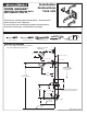
Turn off hot and cold water supplies.
Loosen HANDLE SET SCREW (1) and pull of
HANDLE (2).
If installed, pull off DECORATIVE SCREW COVER (3).
Remove two SCREWS (4) holding ESCUTCHEON (5)
and remove ESCUTCHEON (5).
Remove CAP (6).
TO GAIN ACCESS TO VALVE FOR SERVICING