
Installation Guide

2
3515 Lakeshore Drive
Saint Joseph, MI 49085
2” Combustion Air /
Vent Pipe
3” Combustion Air /
Vent pipe
Max
Max
15’
(4.5M)
2
100’
(30M)
6
NOTE: Ensure all vents are properly supported.
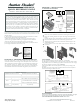
I. Power Connections
II. Dip Switch
A. OPEN THE WATER AND GAS LINE VALVES
B. ADJUST CONTROL PANEL ON WATER HEATER FRONT COVER
C. MEASURING INLET GAS PRESSURE
LP GAS
NATURAL GAS
Minimum Pressure
3.5” WC
Minimum Pressure
3.5” WC
Maximum Pressure
14” WC
Maximum Pressure
14” WC
NOTICE
NOTE TO CONSUMER: PLEASE KEEP ALL INSTRUCTIONS FOR
FUTURE REFERENCE.
Dip Switch
Off
On
1 – 3
Not used
Not used
Not used
Not used
4
5
Gas Type
LP
NG
6
High Fire
Normal
High Fire
7
Low Fire
Normal
Low Fire
1. Check Installation completely.
2. Check for leaks along Gas Pipes & Installation.
3. Check Exhaust Vent and Intake Pipe Instal lation for leaks. Ensure all vent pipes
are properly supported.
4. Check Condensate Drain Installation.
5. Ensure DIP switches are properly installed.
6. Check the Electrical Supply Power connections are correct.
7. Check Burner Flame for proper operation.
WARNING
The pipe size used for the supply of heated water should be the same size
used for the water return pipe. The correct size of the hot water supply
pipe should be ¾” diameter. Install tankless isolation valves to avoid future
service.
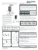
E. CONDENSATE DRAIN CONNECTION
Condensate must be drained in accordance with all
local codes & regulations. Follow local codes
regarding the disposal of condensate & drainage.
Diagram left; (1) Condensate to neutralizer, (2) to
floor drains, (3) to bathtub, (4) to condensate
pump. Use only corrosion resistant materials for
the condensate drain lines, such as ½” PVC,
CPVC, Polypropylene, or the included plastic hose.
If a neutralizer is installed, periodic replacement of
the limestone (or neutralizing agent) will be
required. The rate of depletion of limestone varies
upon usage of the water heater. During the first
year of operation, check the neutralizer every few
months for depletion.
F. VENTING
Acceptable Vent Lengths (PVC, CPVC, PP)
Models
TCWH180S-AS
TCWH199S-AS
Maximum
Number of
Elbows
Maximum
Number of
Elbows
G. POWER CONNECTIONS & DIP SWITCH
Ensure that all electrical connections and wiring are installed in accordance with
all local codes. In the absence of local codes, follow the National Electrical Code,
NFPA 70, and/or CSA C22.1 Electrical Code-Part 1 in Canada. For your safety,
turn off the electrical power supply at the service entrance panel before making
any electrical connections to avoid possible electrical shock hazard. Failure to do
so may result in property damage, severe personal injury, or death.
NOTE: DO NOT disconnect the power supply during normal water heater
operation.
Ensure water heater is powered ON. Press & hold the button for standby
mode. Current ‘DHW’ set-point will display and flash. Concurrently, the caution
mark ‘H’ will display. Current ‘DHW’ set-point can be changed by rotating the dial.
After changing the temperature, press the Center Button to save settings.
NOTE: Refer to Installation Manual when adjusting gas pressure.
1. The water heater and its individual shutoff valve must be disconnected from
the gas supply during pressure testing of the system at test pressures greater
than ½ psi (3.5 kPa).
2. The water heater must be isolated from the gas supply by closing the manual
shutoff valve during pressure testing of the gas supply at test pressures equal to
or greater than ½ psi (3.5 kPa).
The minimum and maximum inlet gas line pressures must meet the requirements
shown below:
Do not attempt to ignite/operate water heater until all connections have been
completed and the heat exchange is filled with water. Doing so will damage the
water heater and void the warranty.
NOTICE: American Standard Water Heaters reserves the right to make product
changes or updates without notice and will not be held liable for typographical
errors in literature.
www.americanstandardwaterheaters.com
TCWH180S-AS / TCWH199S-AS REV 06/16
CHAPTER 5 – FINAL CHECK
CHAPTER 4 – AFTER INSTALLATION
12" OVER
MAXIMUM SNOW
LEVEL OR 24" -
WHICHEVER IS
GREATER
VENT KIT
EXHAUST
MAINTAIN 12"
MINIMUM
CLEARANCE ABOVE
HIGHEST ANTICIPATED
SNOW LEVEL OR
GRADE, WHICHEVER IS
GREATER
IMPORTANT:
INTAKE LEG
MUST
BE FACING UP
INTAKE
MAINTAIN 12"
MINIMUM
CLEARANCE ABOVE
HIGHEST
ANTICIPATED SNOW
LEVEL OR GRADE,
WHICHEVER IS
GREATER
IMPORTANT:
INTAKE LEG MUST
BE FACING UP
CONCENTRIC VENT KIT
CONCENTRIC VENT KIT
1” MIN.
EXHAUST
Relief Valve
Gas Valve
Isolation Valve
Cold Water Inlet Line
Hot Water Outlet Line
Gas Supply Line
Discharge Pipe
Condensate Drain Pipe