
Installation Guide

- 2 -
OFF
UP
4
2
UP
1
1
2
UP
1
PLASTER
GUARD
Figure 2.
Figure 1.
Figure 1a.
4
3
OFF
1
Figure 2a.
4
3
2
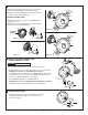
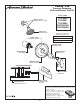
• Install HANDLE (1) by pushing it onto CARTRIDGE STEM (2)
and tightening SET SCREW (3) from below with 2.5 mm
Hex Wrench supplied.
HANDLE INSTALLATION
4
M965931 Rev. 1.3 (3/20)
3
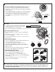
INSTALL TUB SPOUT, SHOWER HEAD,
SHOWER ARM WITH FLANGE
• Remove pipe cap and plug from shower and tub rough piping.
• Slip TUB SPOUT (1) onto tub nipple and tighten with 2.5 mm Hex Wrench.
CAUTION: Protect nish on TUB SPOUT when installing.
• Install SHOWER ESCUTCHEON (2) onto SHOWER ARM (3). Apply sealant
or Teon tape to threads on both ends of SHOWER ARM (3) and thread
longer leg of SHOWER ARM (3) into shower elbow.
• Thread SHOWER HEAD (4) onto SHOWER ARM (3).
CAUTION: Protect nish on SHOWER HEAD and ARM when installing.
• Slip ADAPTER (5) onto CARTRIDGE (6) and thread SCREW (7) on.
CAUTION
Protect nish on SHOWER HEAD
and TUB SPOUT when installing.
PIPE
PLUG
4
3
2
SHR.
ELBOW
TUB FILLER
NIPPLE
5
7
1-1/2" REF.
2.5 MM HEX
WRENCH
6
1
OFF
3
2.5 MM HEX
WRENCH
1
OFF
2
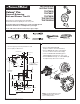
• Figure 1. Remove plaster guard from valve. Push CAP (1)
over VALVE CARTRIDGE (2) until seated against stop.
• Figure 2. Push ESCUTCHEON (3) onto CAP (1) and attach
to valve body with LONG SCREWS (4).
THIN WALL INSTALLATION
• Figure 1a. Push CAP (1) over VALVE CARTRIDGE (2) until
seated against stop.
• Figure 2a. Push ESCUTCHEON (3) onto CAP (1) and attach
to valve body with LONG SCREWS (4).
STANDARD WALL INSTALLATION