Operation Maintenance Manual OM 751 Group: Unit Ventilator Part Number: 106506304 Date: August 2002 II™ Unit MicroTech Ventilator Controls for AAF -HermanNelson Classroom Unit Ventilators ® Supercedes: New ® DX Cooling Only – Software Model UV05 Used with AAF-HermanNelson Classroom Unit Ventilator Model AVV – Floor Mounted Model AHV – Ceiling Mounted Model AZV, AZU – Floor Mounted Self Contained Air Conditioner IMPORTANT Before unit commissioning, please read this publication in its entirety.
TABLE OF CONTENTS Abbreviations Table ......................................................... 3 Safety Information ........................................................... 4 Introduction .................................................................. 5 Getting Started ............................................................... 5 Using the Local User Interface (LUI) ............................................. 5 2-digit 7-segment display ........................................................
Exhaust Fan On/Off Signal ............................................... 26 UVC Input and Output Table .............................................. 27 Diagnostics and Service .................................................. 27 Alarm and Fault Monitoring ......................................................... 27 Space Temp Sensor Failure ................................................... 28 DX Pressure Fault ..................................................................
SAFETY INFORMATION Follow all safety codes. Wear safety glasses and work gloves. Use a quenching cloth for brazing operations. Have a fire extinguisher available. Follow all warnings and cautions in these instructions and attached to the unit. Consult applicable local building codes and National Electrical Codes (NEC) for special requirements. Recognize safety information. When you see a safety symbol on the unit or in these instructions, be alert to the potential for personal injury.
INTRODUCTION This manual contains information regarding the MicroTech II™ control system used in the AAF®-HermanNelson® Unit Ventilator product line. It describes the MicroTech II components, input/output configurations, field wiring options and requirements, and service procedures. For installation and general information on the MicroTech II Unit Ventilator Controller, refer to the appropriate installation and maintenance bulletin, see Table 2.
NOTICE NOTICE The UVC archives each change to the LUI Fan and Mode buttons. When the On/Stop button is used to bring the unit out of Off mode, the UVC will implement the last active fan and unit modes. The setpoint offset is cleared after every power cycle. When changing the setpoint offset after a power cycle, or for the first time, this cleared value will be shown as the highest allowed value (5°F / 3°C) but will not be an actual offset value.
LUI Menu Reference Figure 5. Changing an LUI Menu Item The LUI menu eases troubleshooting and simplifies UVC configuration as the most common parameters and system status values can be accessed without the need of a Personal Computer or network interface. The LUI menu is accessed via an unmarked, Hidden button. This Hidden button is located behind the letter “h” in the MicroTech II logo on the LUI face. The LUI menu consists of two levels.
Table 6. LUI Menu Item List (Continued) Two Digit Display LUI Menu Item List Abr. Economizer Enable Description 05 Set economizer status: 0 = disable, 1 = enable. RW x 1 Default Economizer OA Temp Setpoint ETS Adjust economizer OA temperature setpoint. RW x 68OF (20OC) Economizer IA/OA Temp Differential ETD Adjust economizer IA/OA temperature differential. RW x 2OF (1OC) Economizer Compare Differential ECD Adjust economizer IA/OA temperature differential.
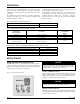
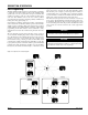
DESCRIPTION OF OPERATION State Programming The MicroTech II UVC takes advantage of state machine programming to define and control unit ventilator operation. State machines define specific states, or modes of operation for each process within the unit ventilator (i.e. heating, cooling, etc.) and contain the specific logic for each state. This eliminates some of the most common problems associated with control sequences such as the possibility of simultaneous heating and cooling, rapid cycling, etc.
UVC Unit Modes The UVC provides several “normal” modes of unit operation, these include Off, Night Purge, Fan Only, Cool, Emergency Heat, Auto, Heat and Cool. Normal UVC modes can contain a single state or several states dependent upon the functionality required for each particular mode. Each UVC state has been assigned a number. This state number can be very helpful when trying to understand which state is currently active within the UVC. The current UVC state number can be viewed using the LUI.
purging process. In the Night Purge mode the space fan will be set to high speed, the OA damper will be set to 100% open, and the Exhaust Fan binary output (see External Binary Outputs) will be set to On. If not set to another mode within 1-hour, the UVC will force itself into the Fan Only mode (see Fan Only Mode). If the space temperature drops below the EHS, and the Emergency Heat function is enabled, the UVC will be forced into the Emergency Heat mode (see Emergency Heat Mode).
Cant Heat State (state number D) HEAT MODE (SUPER STATE) The Cant Heat state is a “non-normal” state that the UVC can go into when Emergency Heat mode is active. Only an IAT or DAT sensor fault during Emergency Heat mode will cause the UVC to make this state active. When in Heat mode the UVC will use auxiliary heat (if field provided and field connected to the unit) as needed to maintain the effective heating setpoint. The LUI or a network connection can be used to force the unit into the Heat mode.
Heat State (state number 5) Low Limit State (state number E) The Heat state is the “normal” state that the UVC will go into when Heat mode is active. The Low Limit state is a “non-normal” state that the UVC can go into while Heat mode is active when the unit reaches 100% heating and still cannot meet the current DATS (see Discharge Air Temperature Control) required to maintain the effective heating setpoint (see Space Temperature Setpoints).
COOL MODE (SUPER STATE) When in Cool mode the UVC will use primary cooling (economizer) and secondary cooling (mechanical, DX) as needed to maintain the effective cooling setpoint (see Space Temperature Setpoints). The LUI or a network connection can be used to force the unit into the Cool mode. Additionally, the UVC when set to Auto mode can automatically force the unit into the Cool mode.
Econ State (state number 3) Econ Mech State (state number 1) The Econ state is a “normal” state that the UVC can go into when Cool mode is active. The Econ state is typically active in the Cool mode when primary cooling (economizer) is available and adequate to meet the cooling requirements. The Econ Mech state is a “normal” state that the UVC can go into when Cool mode is active.
Mech State (state number 2) CANT COOL STATE (STATE NUMBER C) The Mech state is a “normal” state that the UVC can go into when Cool mode is active. The Mech state is typically active in the Cool mode when primary cooling (economizer) is not available and secondary cooling (compressor) is available. The Cant Cool state is a “non-normal” state that the UVC can go into when Cool mode is active.
Low Limit State (state number F) Pressurize Mode The Low Limit state is a “non-normal” state that the UVC can go into while Cool mode is active. The Low Limit state typically follows the DA Heat state when the UVC has reached 100% heat and still cannot maintain VCLL. When in Pressurize mode the UVC will use the IAF, OAD, and exhaust output as needed to pressurize the space. The UVC stops all normal heating and cooling but does allow emergency heat if required.
Table 9.
OCCUPIED MODE The occupied mode is the normal day time mode of UVC operation. During occupied mode the UVC will use the occupied heating and cooling setpoints, the OAD will operate normally, and by default the IAF will remain on. UNOCCUPIED MODE The unoccupied occupancy mode is the normal night time mode of UVC operation. During unoccupied mode the UVC will use the unoccupied heating and cooling setpoints, the OAD will remain closed, and the IAF will cycle as needed for heating or cooling.
LUI SETPOINT OFFSET ADJUSTMENT EFFECTIVE SETPOINT CALCULATION EXAMPLES The LUI can be used to make adjustments to the value of the Setpoint Offset Input variable. See “Using the LUI to adjust Setpoint Offset”. The UVC calculates the effective setpoint (Effective Setpoint Output) based upon the six occupancy setpoints for heating and cooling, occupancy mode, and the value of the network variables Space Temp Setpoint Input, Setpoint Offset Input and Setpoint Shift Input.
PI Control Loops The MicroTech II UVC uses PI-loop control for heating, cooling and ventilation processes within the unit ventilator. As many as six PI algorithms may be used for software model 05, dependent upon the unit ventilator configuration. The UVC uses “single” and “cascading” PI loops where needed. Table 15.
PI CONTROL PARAMETERS Associated with each PI loop is a set of two adjustable PI parameters. These parameters are “Proportional Band” and “Integral Time”. When the unit ventilator is properly sized for the space, the factory settings for these parameters will provide the best and most robust control action. See Figure 20. If field problems do arise, first ensure these parameters are set back to the factory default settings.
Indoor Air Fan Operation The UVC supports a 3-speed IA fan: Low, Medium, and High. The UVC will calculate the effective fan speed and operation based upon the unit mode, the occupancy mode, and the values of several network variables. AUTO MODE The UVC is provided with a user selectable auto fan mode feature. When in auto fan mode, the UVC uses the space temperature PI loop to automatically adjust the fan speed as needed to maintain space temperature.
Temperature Comparison with Enthalpy Comparison Economizer (optional) The UVC uses four configuration variables to determine if the economizer can be used: Economizer OA Temp Setpoint, Economizer Temp Differential and Economizer OA Enthalpy Setpoint, and Economizer EnthalpyDifferential. See Table 19. NOTICE The CO2 DCV function can increase the OA damper position past that required by the economizer and vice versa. NOTICE Table 19.
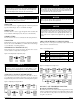
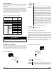
Figure 25. Compressor Envelope in Self-Contained Units (Indoor Air Coil) Evaporator Temperature DX Cooling 2 1 Condenser Temperature Floating-point Actuator Auto-Zero, Overdrive and Sync The UVC at power-up will auto-zero all floating-point actuators (OA damper) before going into normal operation to ensure proper positioning, this can take as long as 150-seconds after power-up.
EXTERNAL BINARY INPUT 3 EXTERNAL BINARY OUTPUT 2 This input can be configured as a ventilation lockout (default) or exhaust interlock signal. This output can only be used as a fault signal. Ventilation Lockout Input Signal This relay output provides a NO, NC, and Common connections that can be used to signal a fault condition. When a fault exists, the UVC will energize this relay output, when the fault or faults are cleared the UVC will de-energize this relay output.
UVC INPUT AND OUTPUT TABLE All UVC input and output connections and their corresponding unit ventilator usage are shown in the following table. Table 21.
DIAGNOSTICS AND SERVICE (continued) SPACE TEMP SENSOR FAILURE ( ) SPACE COIL DX TEMP SENSOR FAILURE ( ) The Space Temp Sensor Failure fault will occur when the UVC detects an open or a short condition from the space temperature sensor. The Space Coil DX Temp Sensor Failure fault will occur when the UVC detects an open or a short condition from the DX temperature sensor.
DIAGNOSTICS AND SERVICE (continued) SPACE CO2 SENSOR FAILURE (OPTIONAL) ( ) The Change Filter Indication will occur when the UVC calculates that the total fan run time has exceeded the allowed number of hours since the last filter change. The following procedure can be used to troubleshoot a suspect humidity sensor. 1. Disconnect the sensor(s)’ output voltage lead from the UVC analog input. 2. Take a humidity reading at the sensor location. 3.
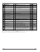
UVC CONFIGURATION PARAMETERS The UVC has been provided with a number of configuration variables as listed in the following table. These configuration variables are stored in UVC non-volatile memory. For a description of supported network variables for each protocol refer to Protocol Data Packet bulletin, see Table 4. NOTICE The software ServiceTools™ can be used to adjust parameters not adjustable through the LUI. Table 26. UVC Configuration Parameters Configuration Parameter Name Abr.
Table 26. UVC Configuration Parameters (Continued) Configuration Parameter Name Abr. Notes Secondary Cool Integral Time Default 600 sec 13.5OF (7.
This document contains the most current product information as of this printing. For the most up-to-date product information, please go to www.mcquay.com. ® ©2002 McQuay International Page 32 of 32 • www.mcquay.