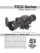
TICO Series THERMAL IMAGING CLIP-ON OPERATOR’S MANUAL (TICO Series) REVISION 5 – SEP, 2014 o p e r a t o r ’s m a n u a l Important Export Restrictions! Commodities, products, technologies and services contained in this manual are subject to one or more of the export control laws and regulations of the U.S. Government and they fall under the control jurisdiction of either the US Department of State or the US BIS-Department of Commerce.
Register your product warranty online at www.atncorp.com/warranty Manual (TICO Series) Revision 5 – September, 2014 The information in this manual furnished for information use only, is subject to change without notice, is not to be construed as a commitment by ATN Corp. ATN Corp. assumes no responsibility or liability for any errors or inaccuracies that may appear in this book. © 2014 ATN Corp. All right reserved.
SAFETY SUMMARY STUDY CAREFULLY THIS MANUAL BEFORE TURNING ON AND OPERATING THIS PRODUCT. CAUTIONS The TICO Series Thermal Imaging Clip-On are precision electro-optical instruments and requires careful handling. To provide safe use of the systems the following instructions should be observed: • Do not dismantle the device. • Keep the device clean; protect it from moisture, sharp temperature drops and shocks. • Be careful not to touch the glass surfaces.
WARNING Do not permanently attach the scope to dynamic-mount applications that continuously transmit vibration (such as on vehicles or heavy machinery). WARNING Do not point the scope directly at any high-intensity objects that you must not view with your eyes (such as the sun or a welding arc). If you do, you will damage the scope. WARNING Operating TICO Series outside of its specified operating temperature range or voltage range can cause permanent damage and will void the warranty.
WARNING Remove the batteries before you store the riflescopes for extended periods (2 weeks or more). WARNING Do not carry batteries in pockets containing metal objects such as coins, keys, etc. Metal objects can cause the batteries to short circuit and become very hot. In the case of lithium batteries, a short circuit could cause them to explode. WARNING Observe battery manufacturer’s guidelines for safe handling and proper disposal of batteries.
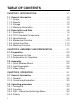
TABLE OF CONTENTS CHAPTER 1. INTRODUCTION. . . . . . . . . . . . . . . . . 1-1 1.1. General Information. . . . . . . . . . . . . . . . . . . . 1.1.1. Scope. . . . . . . . . . . . . . . . . . . . . . . . . . . 1.1.2. Reports . . . . . . . . . . . . . . . . . . . . . . . . . . 1.1.3. Storage . . . . . . . . . . . . . . . . . . . . . . . . . . 1.1.4. Warranty Information. . . . . . . . .
3.2.5. Brightness. . . . . . . . . . . . . . . . . . . . . . . . . 3-8 3.2.6. Zoom. . . . . . . . . . . . . . . . . . . . . . . . . . . . 3-8 3.2.7. Manual Image Refresh / Calibration . . . . . . . . . . . . 3-9 3.2.8. Reticle Color . . . . . . . . . . . . . . . . . . . . . . . 3-10 3.2.9. Reticle Pattern . . . . . . . . . . . . . . . . . . . . . . 3-10 3.2.10.
HOW TO USE THIS MANUAL • Usage You must familiarize yourself with the entire manual before operating the equipment. Read and follow all warning notices. • Manual Overview The table of contents includes the paragraph number, paragraph title, and page number. An index provides additional references to the subject contents.
CHAPTER 1 INTRODUCTION 1-1
1.1. GENERAL INFORMATION 1.1.1. SCOPE This manual contains instructions for use in operating and maintaining the TICO Thermal Imaging Clip-On. Throughout this manual, the TICO Series will be referred to as the scope or TICO. 1.1.2. REPORTS Reports from the user on recommendations for improvements are encouraged. Send reports to the address below. American Technologies Network Corp. 1341 San Mateo Avenue South San Francisco, CA 94080 (800) 910-2862 (650) 989-5100 (650) 875-0129 fax info@atncorp.com www.
3 YEAR PRODUCT WARRANTY This product is guaranteed to be free from manufacturing defects in material and workmanship under normal use for a period of 3 (three) years from the date of purchase. In addition the uncooled thermal sensor array carries a 10 year warranty.
or consequential damages, including, but not limited to, lost income, lost revenue, or lost profit, whether such damages were foreseeable or not at the time of purchase, and whether or not such damages arise out of a breach of warranty, a breach of agreement, negligence, strict liability or any other theory of liability.
1.2. DESCRIPTION AND DATA 1.2.1. DESCRIPTION a. Purpose Representing the latest advancement in thermal imaging technology, the ATN TICO-Series thermal clip-on gives your daytime scope thermal imaging capability in a matter of seconds. The ATN TICO-Series mounts in front of a daytime scope to enable thermal vision in day or nighttime operation. No shift of impact, no need to rezero nor change of eye relief occurs.
• • • • 1-6 Polarity: white hot / black hot / color Thermal images viewable in up to 12-tone color pallet Ten-step brightness control Batteries: (2) 3V lithium (CR123A).
1.2.2. TICO STANDARD COMPONENTS The TICO standard components are shown in Figure 1.1. and presented in Table 1.1. FIGURE 1.1. TICO STANDARD COMPONENTS TABLE 1.1. TICO STANDARD COMPONENTS ITEM DESCRIPTION QTY 1 Scope The thermal imaging scope. 1 2 Quick Release Mount Used to mount scope to weapon. 1 3 Hard Storage Case A protective case used for shipping/storing TICO and accessories. 1 4 Lens Tissue Uses for cleaning of lenses surface.
1.2.3. SPECIFICATIONS The following tables provide information pertaining to the operational, electrical, mechanical, optical and environmental characteristics for the sights. TABLE 1.2.
ITEM TICO-336 TICO-640 Waterproof Battery type Battery Life Waterproof / Dustproof 2 x CR123A 4+ h Mounting bracket MIL-STD 1913 Picatinny (Quick Detach) Video output Low Battery Indicator Iconology Housing Objective lens Dimensions (with mount) Weight Warranty Yes Yes Quick access via Icon driven feature controls Aircraft Aluminum 6061 T6 w/hard anodized coating 50mm, full MIL SPEC, with DLC coating 189 x 69 x 65mm/7.45 x 2.7 x 2,56” 0.64 kg / 1.
1.2.4. MECHANICAL FUNCTION The mechanical adjustments of the TICO sights allow for physical differences between individual operators using the system. The scope functions include the Keypad, Output Connector, Eyepiece Diopter Adjustment Ring, Focusing Ring, Battery Module, Accessory Rail, and Weapon Mount. The controls are identified in Figure 1.2. KEYPAD WEAPON MOUNT FOCUS KNOB BATTERY MODULE ACCESSORY RAIL WEAPON MOUNT RELEASE FIGURE 1.2. TICO MECHANICAL CONTROLS 1.2.5.
ing. The signal processing circuitry translates the infrared detector data into an image that can be viewed on the built-in OLED display. The image is observed through an eyepiece by operator. 1.2.6. ELECTRICAL FUNCTION The electronic circuit is powered by replaceable two 3V lithium batteries (CR123A). Power from the batteries is supplied to the components through the Power button.
1-12
CHAPTER 2 ASSEMBLY AND PREPARATION 2-1
2.1. PREPARATION 2.1.1. PREPARATION FOR USE This chapter contains the information necessary to prepare the scope for operation. This includes unpacking, examination for damage, and batteries installation. a. Unpacking The following steps must be accomplished prior to each mission where the sight is used. 1. Open carrying case, remove the scope and check contents for completeness. 2. Inspect the scope for obvious evidence of damage to optical surfaces, body, eyecups, operation buttons, etc.
3. Replace battery cap module of the housing. Screw knob clockwise until finger tight. Do not over tighten as it will be difficult to remove the next time you replace batteries. BATTERY MODULE FIGURE 2.1. LOADING BATTERY MODULE 2.1.2. EXAMINATION FOR OPERATION Before getting started, make sure to follow these steps: 1. Push Power button on the scope. 2. Make sure that the luminance in ocular is present. 3. Observe the scene, and adjust the diopter and/or lens for optimal image clarity.
2.2. ASSEMBLY 2.2.1. QUICK RELEASE MOUNT Quick Release Mount (QRM) is used for fast installation/removing the TICO on MIL-STD-1913/Picatinny rail. NOTE Optical axes of the TICO and the riflescope should be matched. Difference of the axes position more than 3 mm is not re-commended. Measure the height of the riflescope axis above the rail. If the difference in the axis heights of the TICO and riflescope is more than 3 mm it is necessary to replace riflescope mounting rings or base by proper ones.
3. Turn the lever backwards (parallel) to close the mount. NOTE If using weaver rails, please consult your gunsmith for modification to rail. 2.2.2. LIGHT SUPPRESSOR Your TICO comes with a rubber light suppressor attachment. To use the light suppressor: 1. Unscrew the external eyepiece ring. FIGURE 2.3. 2. Next, place the small diameter of the rubber light suppressor over the threaded portion of the eyepiece. FIGURE 2.4. 3. Now the TICO can be mounted ahead of a day scope with the light suppressor.
2.2.3. VIDEO OUTPUT This version of the TICO is equipped with the added feature of being able to connect directly to a remote video monitor or recorder via an integrated video output port. 1. Connect the video cable to the sights video output port. 2. Connect the video cable to the appropriate recording device. Operation: 1. Turn on the system by pressing the POWER button. 2. Let screen image settle before transferring video to the monitor. VIDEO OUTPUT PORT 3.
CHAPTER 3 OPERATION 3-1
3.1. GENERAL INFORMATION 3.1.1. GENERAL This section contains instructions for operation of TICO. The function of controls and indicators is explained. CAUTION The TICO scope is a precision electron-optical instrument and must be handled carefully at all times. 3.1.2. CONTROLS AND INDICATION The TICO is designed to adjust for different users and corrects for most differences. The controls for the scope are shown or described in Figure 3.1. and Tables 3.1.
TABLE 3.1. CONTROLS AND INDICATION ITEMS CONTROLS AND INDICATORS FUNCTIONS 1 POWER Button Controls TICO power. To turn the unit on and off press the button 2 ENTER Button Used to select or enter selection 3 Up Arrow Calibration, Reticle Color 4 Down Arrow Brightness, Saved Ballistic Profile 5 Left Arrow Color, Reticle On/Off 6 Right Arrow Calibration, Reticle adjustment 3.2. OPERATING PROCEDURE 3.2.1. TURNING ON Open the objective lens cover.
NOTE During the warm-up time, a logo comes into view on the monocular display. Next the thermal image replaces the logo. FIGURE 3.2. SWITCHBOARD OF TICO 3.2.2. FOCUSING 1. 2. 3. 4. To focus the scope you need to focus your dayscope first. Once the TICO is mounted in front of your dayscope turn unit on. Calibrate the thermal device (see page 3-9). The front lens should be readjusted for viewing objects at different distances.
NOTE The front lens should be readjusted for viewing objects at different distances. Rotate the focusing ring clockwise for far focus, counterclockwise for near focus. 3.2.3. ISM – INTERACTIVE SYMBOLOGY MENU The TICO features the all new ISM interactive symbology menu that enables you to easily navigate through the features and modes without having to go into a complex menu structure.
RETICLE COLOR RETICLE ADJUSTMENT RETICLE ON/ OFF SAVED BALLISTIC PROFILE FIGURE 3.5. ISM RETICLE MENU FIGURE 3.6.
3.2.4. POLARITY The function of polarity switching is accessible only in Black and White models. WHITE HOT BLACK HOT FIGURE 3.7. DISPLAY POLARITY MODES Polarity: Polarity is the most common used thermal color modes. The function of polarity switching is accessible only in Black and White models. Polarity button switches the direct display mode into the reverse one, i.e. from hot-white/cold-black into hot-black/coldwhite mode.
IRONBOW COLOR 1 GLOBOW FIGURE 3.8. COLOR MODES 3.2.5. BRIGHTNESS Brightness allows you to dim or increase the brightness of the display. To cycle through the BRIGHTNESS steps go to ISM Main menu and push the down arrow button for brightness adjustment. Each short push of the buttons will cycle through the BRIGHTNESS modes, correspondingly, in stepwise way. NOTE Levels 1 to 6 range from full dim to full bright. 3.2.6.
NOTE Resolution decreases with each step of digital magnification. The reticle has a built in compensation to shift and stay on the target during digital zoom operations as depicted in Figure 3.9. NO ZOOM RETICLE ON TARGET 2X ZOOM RETICLE SHIFTS 2X 4X ZOOM RETICLE SHIFTS 4X FIGURE 3.9. ZOOM 3.2.7. MANUAL IMAGE REFRESH / CALIBRATION Degradation of the image (image blurring) is caused by charge accumulation on the detector array.
DURING CAL CORRECT VIEW CORRECT CAL IF LENS IS COVERED INCORRECT CAL IF LENS IS NOT COVERED FIGURE 3.10. CALIBRATION (NUC) 3.2.8. RETICLE COLOR Your scope has Four reticle colors to choose from: red, green, white, black, the latest firmware also includes many bonus colors. To select reticle colors go to ISM Reticle menu and push Up arrow button to cycle through the reticle colors. RED WHITE BLACK GREEN FIGURE 3.11. RETICLE ADJUSTMENT 3.2.9.
This will bring you to ISM Reticle Adjustment menu which will allow you to do your vertical and horizontal adjustments. To adjust vertical and horizontal adjustments for the scope use corresponding arrows: • Up Up arrow for up adjustment • Down arrow for down adjustment • Left arrow for left adjustment • Right arrow for right adjustment FACTORY DEFAULT ELEVATION ADJUSTMENT WINDAGE ADJUSTMENT FIGURE 3.12. WINDAGE AND ELEVATION ADJUSTMENTS 3.2.11.
3.2.12. SIGHTING-IN THE CLIP-ON SCOPE 1. Insure your optical day scope is sighted in to your weapon. 2. If possible, lock down the weapon in a shooting vice, this will insure the highest level of accuracy. Now place the day scope reticle on a thermal target at the same distance that the day scope is sighted in to. 3. Attach the TICO to the weapon in front of the day scope. 4. At x1 zoom, press the “ENTER” button to get to the Reticle menu (Figure 3.2.
5. Adjust the TICO reticule until it is exactly on top of the day scope reticle(still at x1 zoom) (Figure 3.16.). FIGURE 3.16. 6. Exit the reticule adjust mode, and save the day scope reticle position to any ballistic profile location (Figure 3.17.). X= 0 Y= 0 1 2 4 3 FIGURE 3.17.
7. Return to the Reticle menu (Figure 3.18.) and scroll through unit the fine line and dot reticle is turned off. Now enter the reticule adjust level. RETICLE COLOR RETICLE TYPE RETICLE POSITION SAVED RETICLE LOCATION FIGURE 3.18. 8. Adjust the TICO image position using the up/down/left/right buttons on the TICO keypad, until the thermal target is centered under the day sight reticle. 9.
CHAPTER 4 MAINTENANCE INSTRUCTIONS 4-1
4.1. PREVENTIVE MAINTENANCE CHECKS AND SERVICES (PMCS) 4.1.1. PURPOSE OF PMCS PMCS is performed daily when in use to be sure that the sight is ready at all times. Procedures listed in Table 4.1. are a systematic inspection of TICO that will enable you to discover defects that might cause the sight to fail on a mission. 4.1.2. FREQUENCY OF PERFORMING PMCS The frequency of performing PMCS is as follows: a. Daily when the sight is in use. b. When it is removed from the case for any reason. TABLE 4.1.
SEQ. NO. ITEM TO CHECK CHECKING PROCEDURE 7 Focus Ring Check to ensure: — the focus ring cannot be moved along the sight body; — there is free rotation of the focus ring (more than 3/4 turn). 8 Rubber Eye-cup Inspect for cuts or tears NOT FULLY MISSION CAPABLE IF: Focus ring able to move along sight body. Focus ring cannot be rotate Rubber Eye-cup torn or cut AFTER CHECKING PROCEDURES 9 Replace protective covers on the lenses. Remove the batteries.
4.2. TROUBLESHOOTING 4.2.1. GENERAL This section contains information for locating and removal most of the TICO operating troubles which may occur. Each malfunction for an individual component or assembly is followed by a list of tests or inspections that will help determine probable causes and corrective action to take. Perform the tests/inspections and corrective actions in the order listed.
4.3. MAINTENANCE PROCEDURES 4.3.1. SCOPE MAINTENANCE The TICO maintenance consists of external inspection of its components for serviceability, cleaning and installation of the standard and optional accessories. Maintenance instructions covered elsewhere in this manual (PMCS, troubleshooting, etc.) are not repeated in this section. CAUTION The TICO is a precision electron-optical instrument and must be handled carefully at all times to prevent damage. 4.3.2. CLEANING PROCEDURES a. Cleaning the scope 1.
4.3.3. PREPARING FOR EXTENDED STORAGE To prepare the TICO for extended storage, perform the following: 1. Check the scope for serviceability as outlined in item 4.1 of this manual. 2. Remove the batteries. 3. Clean the scope and accessories. 4. Replace all items in the case.
4-7
For customer service and technical support, please contact American Technologies Network Corp. 1341 San Mateo Avenue, South San Francisco, CA 94080 phone: 800-910-2862, 650-989-5100; fax: 650-875-0129 www.atncorp.