Service Handbook COMMERCIAL GAS WATER HEATERS MODELS (A)BCG385T500-8N & (A)BCG38T500-8P INSTALLATION CONSIDERATIONS SERIES 120/121 - PRE SERVICE P.O. Box 1597 Johnson City, TN 37605 CHECKS - WATER HEATER CONSTRUCTION OPERATION & SERVICE - TROUBLESHOOTING INSTALLATION CONSIDERATIONS - PRE SERVICE CHECKS - OPERATION & SERVICE -TROUBLESHOOTING SERVICING SHOULD ONLY BE PERFORMED BY A QUALIFIED SERVICE AGENT. PRINTED IN THE U.S.
COMMERCIAL GAS WATER HEATER SERVICE MANUAL TABLE OF CONTENTS INTRODUCTION ............................................................3 Gas Control Valve/Burner Area View ......................18 Qualifications ...........................................................3 Blower Prover Switch - Settings .............................19 Service Warning........................................................3 Thermostat and Ignition control Board View ...........20 Service Reminder .......................
INTRODUCTION INTRODUCTION This Service Manual is designed to be an aid in servicing and troubleshooting American models (A)BCG385T500-8N/8P Series 120/121 commercial water heaters. The instructions and illustrations contained in this service manual will provide you with troubleshooting procedures to verify proper operation and to diagnose and repair common service problems. This Service Manual does not replace or supersede the instruction manual that came with the water heater.
REQUIREMENTS REQUIREMENTS INSTRUCTION MANUAL Have a copy of the instruction manual that came with the water heater on hand for the model being serviced. Instruction manuals can be obtained at the American Water Heaters web site (www.americanwaterheater.com) or by calling technical support at 800-456-9805. Installation information given in this service manual is not a complete installation instruction.
INSTALLATION CONSIDERATIONS INSTALLATION CONSIDERATIONS Installation information given in this service manual IS NOT a complete installation instruction. Installation information covered in this service manual has a limited focus as it applies to servicing. This service manual does not replace or supersede the Instruction Manual that came with the water heater. Always refer to the instruction manual that came with the water heater for complete installation instructions.
INSTALLATION CONSIDERATIONS Table 1 NATURAL GAS 10” W.C. (2.49 kPa) 5.2” W.C. (1.29 kPa) 3.5” W.C. (0.87 kPa) ‡ Maximum Supply Gas Pressure † Minimum Supply Gas Pressure * Manifold Gas Pressure PROPANE (LP) GAS 12” W.C. (2.99 kPa) 11” W.C. (2.74 kPa) 10” W.C. (2.49 kPa) ‡ Maximum supply pressure; readings are taken while gas is not flowing (static pressure) AND while gas is flowing (dynamic pressure). Supply pressure must never exceed this maximum value.
INSTALLATION CONSIDERATIONS Insufficient Make-up Air, Negative Air Pressure, and Downdrafts A lack of combustion and ventilation air can create a negative ambient air pressure in the installed space. The vent system on one or more gas fired appliances can experience down drafts due to the outdoor air pressure being greater than the ambient air pressure in the installed space.
INSTALLATION CONSIDERATIONS Make-up Air: Direct Communication with Outdoors A fresh supply of make-up air for combustion can be supplied to the water heater through make-up air ducts, which directly communicate with the outdoors. (Not Direct Vent.) Two openings are required: one within 12 inches of the top of the enclosure and one within 12 inches of the bottom of the enclosure.
INSTALLATION CONSIDERATIONS Contaminated Air Carefully review the warnings concerning contaminated combustion and ventilation air in the instruction manual that came with the water heater. Combustion air that is contaminated can greatly diminish the life span of the water heater and water heater components such as burners, igniters, flue baffles and vent system components.
INSTALLATION CONSIDERATIONS Table 2 MINIMUM CLEARANCES TO COMBUSTIBLE SURFACES “A” - Right Side 5” (12.7 cm) “B” - Left Side 5” (12.7 cm) “C” - Back 5” (12.7 cm) A, B, and C clearances to non-combustible surfaces is “0” inches. A 20” clearance to cover remains unchanged. CLEARANCES (EXTERIOR) The illustration below shows the required clearances for venting units using natural draft venting.
INSTALLATION CONSIDERATIONS VENTING The (A)BCG385T500-8N/8P water heater is classified by ANSI as a Category I (noncondensing, negative pressure venting) appliance. It is approved for type B vent. The blower (draft inducer) does not pressurize the exhaust. NOTE: This section of the service manual is not a complete venting installation instruction. Refer to the instruction manual that came with the water heater; ensure the venting has been installed per all instruction manual requirements.
OPERATION AND SERVICE OPERATION AND SERVICE SEQUENCE OF OPERATION 1. Call for heat is activated when temperature sensed from Thermistor Probes falls below the Thermostat setting. 2. Blower (Draft Inducer) is energized. 3. Ignition Control Board verifies that the Blower Prover Switch is closed and that the Blower (Draft Inducer) is operating. 4. Igniter is energized. 5. Gas Valve is energized and burners ignite 6. Ignition Control Board verifies flame at burners. 7. Water is heated to Thermostat set point.
OPERATION AND SERVICE ELECTRICAL SEQUENCE 1. Switch Power on to unit. 2. Thermostat calls for heat. 3. Ignition Control Board performs diagnostic check on system components. 4. On completion of diagnostics check, the Ignition Control Board energizes the Blower (Draft Inducer). 5. The Blower (Draft Inducer) begins drawing air through appliance, closing the Blower Prover Switch. 6. On completion of Blower Prover Switch engagement, the Ignition Control Board begins the ignition cycle. 7.
OPERATION AND SERVICE WIRING DIAGRAM R BK BK INDUCER R UPPER PROBE/ ECO BLOWER PROVER PRESSURE SWITCH W BK Y THERMOSTAT R TO EARTH GROUND R BL BR IGNITION BOARD R BK LOWER PROBE 1a 1 1b R W HOT 120 VAC NEUTRAL EARTH GROUND G IGNITER/FLAME SENSOR NOTE: Must be properly grounded and have correct polarity connections.
OPERATION AND SERVICE OPERATING SEQUENCE - FLOW CHART Power On Call for Heat Self diagnostic check is performed (Correct state of Blower Prover Switch and ECO is verified) (polarity , earth ground , and Igniter presence are verified ) NO Control Locks Out - LED Displays 2, 6, or 8 Flash Error Code (See Error Code Chart ) YES Blower (Draft Inducer) Motor is Energized Blower Prover Switch (N.O.) Contacts Close at – 2.85“ W.C. ± 0.13” W.C.
OPERATION AND SERVICE GAS CONTROL VALVE This gas valve is a 24 volt AC combination-step opening valve. It includes two valves assembled in parallel, connected by a wiring harness. Note that the valves have fixed pressure regulation and are not adjustable. However, the manifold (outlet) pressure is adjustable as described on the next page. IMPORTANT: • For complete device shut-off, both gas control knobs must be in the OFF position.
OPERATION AND SERVICE Manifold Pressure Adjustment The main gas regulators are found beneath the silver or black cap screws. (Natural Gas valves have silver caps; Propane valves have a black caps). Remove the caps to access the outlet (manifold) pressure adjustment screw. IMPORTANT: Ensure that the outlet pressure matches the manifold pressure that is listed on the water heater rating plate. • Natural Gas valves are factory preset to 3.5 inches W.C.
OPERATION AND SERVICE GAS CONTROL VALVE/BURNER AREA VIEW Honeywell Gas Valve Rollout Shield Main Burner Shield Radiation Shield Main Burner with Hot Surface Igniter (HSI) mounted Figure 14 Table 3 HOT SURFACE IGNITER (HSI) Volts AC Nominal 80 VAC Ohms Resistance 11.0 - 20.0 @ 77° F (25° C) NOTICE FLAME ROD CROSSES PATH OF FLAME 0.1” to 0.25”.
OPERATION AND SERVICE BLOWER PROVER SWITCH - SETTINGS Vent Connection Exhaust/Outlet Blower Prover Switch Optional Hot Water Outlet Blower (Draft Inducer) Figure 15 Table 4 BLOWER PROVER SWITCH TABLE Model (A)BCG385T500-8N/8P Pressure Setting to Close Switch (Inches W.C.) -2.85” ± 0.13” NOTE: The Blower Prover Switch contacts are normally open and will close on a fall in pressure. This will be a negative pressure (i.e., a vacuum).
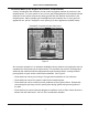
OPERATION AND SERVICE THERMOSTAT AND IGNITION CONTROL BOARD VIEW Figure 16 Servicing should only be performed by a Qualified Service Agent 20
OPERATION AND SERVICE WHITE RODGERS INTEGRATED CONTROL - THERMOSTAT Display LED Label Display LEDs Temperature Adjustment Dial To Upper Temp. Probe ECO Manual Reset Button To Ignition Control Board E3 E1 E4 To Lower Temp.
OPERATION AND SERVICE PRE-SERVICE CHECKLIST Use the following checklist BEFORE you begin servicing the water heater. 1. Have you removed the cover from the controls? • Did you take notice of the status lights on the upper water heater control? • Did you take notice of the red LED in the upper left corner of the lower ignition control? 2.
TROUBLESHOOTING TROUBLESHOOTING IGNITION CONTROL BOARD: ERROR CODES The White Rodgers ignition control board will display a flashing error code with an LED light located on the upper left corner of the Ignition Control Board (Figure 18) when there is a problem. There is a distinctive pause between a series of on/ off flashes (1 to 8 flashes) when there is a problem. The following information describes the meaning of these error “flash” codes and what should be checked and/or repaired.
TROUBLESHOOTING 3 FLASHES Blower prover (air pressure) switch failed to close its normally open contacts after blower (draft inducer) was energized. Blower will run indefinitely, waiting for the blower prover switch circuit to close. 1 Check air pressure reading at blower prover switch sensing port on blower fan housing with manometer (digital preferred); blower must develop at least -2.85” W.C. (negative pressure) before blower prover switch contacts will close.
TROUBLESHOOTING 4 Check molex plug connector between igniter/flame sensor assembly and control board; Also check flame sense (12 pin) plug connection at control board. 8 FLASHES Igniter not sensed and/or water heater not grounded. 1 Test igniter resistance. It should should be 11 - 20 ohms. Replace igniter if open continuity. 2 Ensure that the water heater is grounded. Check all ground wires on heater and controls. 3 Check molex plug connector between igniter/flame sensor assembly and control board.
TROUBLESHOOTING INTEGRATED HEATER CONTROL: DISPLAY LIGHTS Power Call for Heat Energy Cut Off Status Reset Status LED STATUS INDICATION ACTION Calling for heat Normal status. No action required. The ECO (Energy Cut-Off) has opened. • Check for excessively hot water (203° F or higher). • Correct the problem No power Check the breaker. Tank is at a set temperature ± 2° F. No action required. • Push the manual reset button. Refer to Figure 17. Tank has cooled below 120° F.
TROUBLESHOOTING TEST 1: 120 VAC TO HEATER CHECK Conditions: • No Green Display “Power” LED on. • Plugs are in receptacles. • Supply power breaker is not open. • On/Off heater switch is on. White Rodgers I t Integrated t dC Control t l TO EARTH GROUND Display LEDs BL BR R BK 1a 1 1b R W HOT 120 VA V C VAC NEUTRAL EARTH GROUND Ignition Control Board IGNITOR/FLAME SENSOR E2 R R (E14) From Heater Control 120 VA V VAC C CIRCUIT FACTORY F FA CTORY INSTALLED T BY INSTALLER T W 120 V.
TROUBLESHOOTING TEST 2: POLARITY CHECK Conditions: • No hot water • Green “Power” LED is on. • Tank is more than 5° F below temperature dial setting. • Red ignition control board diagnostic LED is flashing 6 times between pauses. • Red, diagnostic “Call for Heat” LED-OFF. Figure 20 TO EARTH GROUND 120 V.
TROUBLESHOOTING TEST 3: CONTINUITY CHECK OF HIGH LIMIT (ECO) Conditions: • Power On – No Hot Water • Red, heater control “Call for Heat” LED – on • Red ignition control board diagnostic LED – 4 Flashes • Note LED Flash Code before resetting water heater control. • See Ignition Control Board: Error Codes. • Turn Power OFF. Figure 22 TEST 3 Continuity check of ECO (energy cut-off, high limit) Black to Black wires of upper probe. Power is off. IF......... Then............
TROUBLESHOOTING TEST 4: UPPER TEMPERATURE PROBE CONTINUITY CHECK Conditions: • Power On - Water below temperature set point. • Red, water heater control “Reset Status” LED-OFF • “Call For Heat” LED off. Upper Temperature probe continuity check TEST 4 Red wire to red wire - Turn supply power “Off” for this test IF......... then............ Test indicates no continuity replace probe. Continuity is indicated Probe should be okay. (Also verify Ohms resistance for water temperature.
TROUBLESHOOTING TEST 5: CALLING FOR HEAT - NO BLOWER OPERATION Conditions: • Power on • Plugs in Receptacles • Red “ Call for Heat” LED - ON • Blower (Draft Inducer) off Note flash code on ignition control board diagnostic LED. Water Heater Control - Thermostat “Call for Heat” LED Indicator Diagnostic LED Indicator 120 Ignition Control Board Ground Figure 24 TEST 5 IF......... then............ Pin 1 to ground check has no voltage • reset control by interrupting power.
TROUBLESHOOTING TEST 6: BLOWER ON, NO IGNITION Conditions: • Power on • Plugs in receptacles • Blower (Draft Inducer) operating • No power to Hot Surface Igniter (HSI). Note LED flash code. Blower Prover Switch Hot Water Outlet Blower Exhaust Blower (Draft Inducer) Check E4 pin 2 to ground Figure 25 TEST 6 24 VAC Check of Blower Prover Switch Circuit IF......... then............ ignition board receptacles E1, Pin 7 to ground shows no voltage replace Ignition board.
TROUBLESHOOTING TEST 7: BLOWER ON, BLOWER PROVER SWITCH CLOSED, NO IGNITER OPERATION Conditions: • Power on, but no power to igniter • Plugs in receptacles • Blower (Draft Inducer) on • 24V at ignition board E1, Pin 10 Check E4 pin 4 to Ground Check E1 pin 10 - 24V Ground Continuity Test Check E4 pin 2 to Ground 4 3 2 1 E4 Plug Ground Figure 26 Voltage check and continuity check of hot surface igniter circuit TEST 7 Continuity check - Power off- Plug removed from E4 receptacles.
TROUBLESHOOTING TEST 8: IGNITER HEATS, NO MAIN BURNER 24 V. E1 Plug to Pin 9 E1 Plug to Pin 12 Figure 27 TEST 8 IGNITER HEATS......NO MAIN BURNER IF......... then............ short heat up time of igniter check control box grounding. Normal warm up (Approximately 20 seconds) No ignition check for 24V from E1, Pin 12 to ground during 4 second trial. If Yes, continue. If No, replace Ignition Board No voltage present E4, Pin 12 to ground replace ignition board.
TROUBLESHOOTING TEST 9: IGNITER HEATS, NO MAIN BURNER Conditions: • Test 8 completed • Turn off power • Disconnect wires from gas valve Inlet Manifold Pressure Tap Manifold Pressure Tap Measure Resistance Between Gas Valve Terminals (Main Valve Solenoid Connections) Outlet Figure 28 TEST 9 IGNITER HEATS – NO MAIN BURNER IF......... then............ Meter reads 0 or 1 • Check meter scale setting; verify that it is set to read between 550 and 650 Ohms.
TROUBLESHOOTING TEST 10: MAIN BURNER IGNITION FOR LESS THAN FIVE SECONDS Conditions: • Power On; plug connected • Main Burner ignites for approximately five seconds, then goes out. • Tests 8 and 9 completed Note the flash code on the ignition board LED. Hot Surface Igniter (HSI) HSI Mounted on Main Burner E1, Pin 2 (From Flame Proving Rod) Figure 29 TEST 10 MAIN BURNER IGNITION FOR LESS THAN FIVE SECONDS IF......... then............
TROUBLESHOOTING TEST 11: WATER HEATER SHUTTING OFF BELOW SETTING Conditions: • Main burner ignited • Stored water is below temperature setting more than 5° F (Tank Average). • Power off • Plug disconnected from heater control board receptacle E3 and E4 E3 E4 Figure 30 TEST 11 WATER HEATER SHUTTING OFF BELOW SETTING (Water Temperature Circuit Check - Continuity) IF......... then............ Continuity check pin to pin of lower temperature probe shows 1 or 0 (E4) See Test 4.
NOTES Servicing should only be performed by a Qualified Service Agent 38
NOTES Servicing should only be performed by a Qualified Service Agent 39
P.O. Box 1597, Johnson City, TN 37605 Phone: 800-456-9805 • Fax: 800-999-5210 www.americanwaterheater.com Copyright © 2010 American Water Heater Company. All rights reserved.