Service Handbook COMMERCIAL GAS WATER HEATERS PO Box 1597, 500 Princeton Road Johnson City, TN 37605 FOR MODELS: BCL3 95T199 6NOX, (A)BCL3 85T275 6NOX, (A)BCL3 85T390 6NOX ULTRA LOW NOx SERIES 100 INSTALLATION CONSIDERATIONS - PRE SERVICE CHECKS CONSTRUCTION - OPERATION & SERVICE - TROUBLESHOOTING SERVICING SHOULD ONLY BE PERFORMED BY A QUALIFIED SERVICE TECHNICIAN PRINTED IN THE U.S.A.
TABLE OF CONTENTS INTRODUCTION . . . . . . . . . . . . . . . . . . . . . . . . . . . . . . . . . . . . . . . . . . . . . . . . . . . . . . . . . . . . . . . . . . . . . . 2 QUALIFICATIONS . . . . . . . . . . . . . . . . . . . . . . . . . . . . . . . . . . . . . . . . . . . . . . . . . . . . . . . . . . . . . . . . . . . . . 2 TOOLS REQUIRED . . . . . . . . . . . . . . . . . . . . . . . . . . . . . . . . . . . . . . . . . . . . . . . . . . . . . . . . . . . . . . . . . . .
INTRODUCTION The service handbook is designed to aid in servicing and troubleshooting American BCL3 Models commercial water heaters in the field. No duplication or reproduction of this book may be made without the express written authorization of the American Water Heaters. The following text and illustrations will provide you with a step by step procedure to verify proper installation, operation, and troubleshooting procedures.
TOOLS REQUIRED • Electrical multimeter capable of measuring continuity/ ohms, ac & dc volts, amperes, microamperes, millivolts, and frequency (hz) • • UEi Model DL289 or equivalent Digital manometer + 60" w. c., resolution 0.01" increments Note: A digital manometer is required for testing pressure switches and can replace a gas pressure gauge, draft gauge or slack tube manometer for checking gas pressure.
INSTALLATION CONSIDERATIONS GAS AND ELECTRICAL CHARACTERISTICS MODELS All Models GAS TYPE Natural GAS SUPPLY PRESSURE MINIMUM MAXIMUM 3.5" WC (0.87 kPa) 14.0" WC (3.45 kPa) VOLTS/HZ AMPERES 120/60 <5 All models require a minimum gas supply pressure of 3.5” W.C. The minimum supply pressure is measured while gas is flowing (dynamic pressure). The supply pressure (dynamic) should never fall below 3.5” W.C.
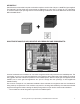
AIR SUPPLY: Stoichiometric or theoretical complete combustion requires 10 cubic feet of air per 1,000 BTU of gas supplied. The National Fuel Gas Code also recommends an additional 2.5 cubic feet of “excess” air. For information on minimum make-up air opening sizes for various building installations, refer to the National Fuel Gas Code NFPA 54/ANSI Z223.1.
MAKE-UP AIR – DIRECT COMMUNICATION WITH OUTDOORS: A fresh supply of make-up air for combustion can be supplied to the water heater through make-up air ducts, which directly communicate with the outdoors. (Not Direct Vent.) Two openings are required: one within 12 inches of the top of the enclosure and one within 12 inches of the bottom of the enclosure. Each opening must have a free area of not less than 1 square inch per 4,000 BTU/Hr of the total input of all appliances within the enclosure.
AIR REQUIREMENTS: For safe operation an adequate supply of fresh uncontaminated air for combustion and ventilation must be provided. An insufficient supply of air can cause recirculation of combustion products resulting in contamination that may be hazardous to life. Such a condition often will result in a yellow, luminous burner flame, causing sooting of the combustion chamber, burners and flue tubes and creates a risk of asphyxiation.
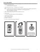
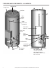
FEATURES AND COMPONENTS – ALL MODELS Outlet Tube Exhaust/Vent Inlet Tube T&P Relief Valve Upper Thermostat Probe/ECO Control Box Assembly Clean Out Cover Lower Thermostat Probe Drain Valve The Eliminator Combustion Blower & Burner Assembly Gas Control Valve 8 Combustion Air Intake Gas Supply Piping: 3/4" NPT Connection Gas Supply Pressure: Natural Gas - Min 3.5" WC, Max 14.
BLOWER AND BURNER ASSEMBLY Fasteners (4) Blower Blower Flange Silicone Gasket Union Adapter Tube Flange Plate Skirt Ring Flange Gasket Burner Gas Control Valve Fasteners (4) Brass Locknuts (3) Brass Nuts/ Lock Washers (4) Burner Gasket Flame Sensor Spark Igniter BURNER REPLACEMENT: 1. Turn off the gas supply and electricity to the water heater. 2. Disconnect the spark ignition cable and ground wire plus the flame sensor wire at their connection points on the flange plate. 3.
7. Remove the 4 brass nuts and 4 lock washers holding the flange plate to the skirt ring flange. 8. Pull the adapter tube/flange plate/burner assembly out of the combustion chamber. Take care not to damage the spark igniter or flame sensor during the removal process. 9. Clean the flange plate and skirt ring flange surfaces to remove any portions of the old skirt ring flange gasket. 10. Support the adapter tube/flange plate/burner assembly in a vertical position with the burner extending downward. 11.
SPARK IGNITER, FLAME SENSOR, SIGHT GLASS The spark igniter and the flame sense rod are shown below. Also shown is the burner sight glass. These features are typical for all models. Burner Flame Sensor Spark Igniter Sightglass SPARK IGNITER / FLAME SENSOR / CONTROL TIMING SPARK IGNITER This water heater is equipped with a spark igniter. Do not damage the ceramic insulator. Inspect the igniter ceramic insulator for any cracks. The spark gap between the spark rod and grounding rod is 1/8".
VENTING INSTALLATION – VENTING CATEGORY AND MATERIALS BCL3 MODELS VENTING Category I • Non-condensing, negative pressure in vent, below atmospheric. Type venting • Must be installed Conventional Vent; uses room air for combustion and discharges flue gases to the outdoor atmosphere through one pipe. Vent materials • B Vent.
EXTERIOR CLEARANCES The illustration below shows the required clearances for venting units using natural draft venting. The vent must extend at least 3 feet above the highest point where it passes through a roof of a building and at least 2 feet higher than any portion of a building within a horizontal distance of 10 feet (for vents of 12 inches in diameter or less). References: NFPA 54/ ANSI Z223.1 may allow reduction to 8 feet with a “listed vent cap.
VENTING TABLES – TECHNICAL VENTING DATA TYPE B GAS VENT Multiple Gas Fired Tank-Type Heaters When venting multiple tank type heaters using Type B vent pipe, follow the installation diagram and tables below which give sizing and data based upon NFPA 54 ANSI Z223.1. MODEL BCL3 95T199 6NOX Input: 199,000 Btu/hr Total Vent Height (Feet) Vent Connector Size: 6 inches 6 8 10 15 20 30 50 100 Input Btuh/hr Rise Vent Connector Diameter (Inches) 199,000 1 Ft. 7 7 7 6 6 6 6 6 199,000 2 Ft.
TYPE B GAS VENT Single Gas Fired Tank-Type Heater When venting single tank type water heater using Type B vent pipe, follow the tables below which give sizing and data based upon NFPA 54 ANSI Z223.1. Total Vent Height (Feet) 6 8 Lateral (Feet) MODEL BCL3 95T199 6NOX Input: 199,000 Btu/hr Vent Connector Diameter: 6 inches Vent Type: Type B Double-Wall Gas Vent Vent Connection: Connected directly to Vent Number of Appliances: Single Appliance Venting: Fan assist Note: Refer to NFPA 54/ ANSI Z223.
OPERATION AND SERVICE SEQUENCE OF OPERATION: 1. Switch power on to unit. 2. Thermostat calls for heat. 3. VFD sends power to Blower. 4. Blower runs at low speed. 5. Combustion Blower initiates air flow through water heater closing the Prover Switch. 6. After 30 seconds, the Ignition Control provides power to the Spark Igniter and Gas Valve. 7. Ignition Control maintains spark for up to 4 seconds and monitors Flame Sensor to determine if Burner is lit. 8.
DIAGNOSTIC SEQUENCE OF OPERATION – FLOW CHART Servicing should only be performed by a Qualified Service Technician 17
SEQUENCE OF OPERATION – FLOW CHART 18 Servicing should only be performed by a Qualified Service Technician
LIGHTING AND OPERATING LABEL FOR YOUR SAFETY READ BEFORE OPERATING WARNING: If you do not follow these instructions exactly, a fire or explosion may result causing property damage, personal injury or loss of life. FLAMMABLE BEFORE OPERATING: ENTIRE SYSTEM MUST BE FILLED WITH WATER AND AIR PURGED FROM ALL LINES. A. This appliance does not have a pilot. It is equipped with an ignition device which automatically lights the burner. Do not try to light the burner by hand. B.
TROUBLESHOOTING COMPLAINT *Water not hot enough. *Insufficient hot water. CAUSE USER Thermostat set too low. Set thermostat dial to a higher temperature Upper and/or lower temperature probe out of calibration. Call qualified agency. Thermostat set too low. Set thermostat dial to a higher temperature *See WATER TEMPERATURE CONTROL WARNING on page Upper and/or lower temperature probe out of 12 of Instruction Manual. calibration. Main manual gas shutoff valve partially closed.
CONTROLS OVERVIEW - CONTROL BOX ASSEMBLY ON/OFF Switch Variable Frequency Drive Digital Thermostat Blocked Inlet Switch Low Speed I/O Module Blocked Outlet Switch High Speed I/O Module Ignition Control Blower Prover Switch Servicing should only be performed by a Qualified Service Technician 21
PRESSURE SWITCHES – ALL MODELS All models are provided with three pressure switches. These switches are essential to the safe and proper operation of the unit. The switches are wired to the Ignition control in series. It is important to understand the purpose of each switch.
BLOWER PROVER SWITCH The blower prover switch is provided on the heater to verify that the fan is operating. It is a positive pressure switch whose electrical contacts are normally open. The blower prover switch electrical contacts will close on a rise in pressure as the blower increases the pressure in the burner. This switch is connected to the blower outlet pressure tap by a piece of silicone tubing. This tubing must be connected in order for the switch to close the electrical contacts.
DISPLAY LIGHTS – DIGITAL THERMOSTAT LED STATUS INDICATION Calling for heat The ECO (Energy Cut-Out) has opened. Normal status. No action required. • Check for excessively hot water (203° F or higher). • Check the resistance of the temperature probes and continuity of the high limit (ECO). No power Check the breaker. Tank is at a set temperature ± 2° F. No action required. Tank has cooled below 120° F. Preceded by “ECO Open” indication. 24 ACTION • Push the manual reset button.
CONTINUITY CHECK OF HIGH LIMIT (ECO) CONDITIONS: • Power On – No Hot Water. • Red, digital thermostat “Call for Heat” LED – On. • Turn Power OFF. Continuity check of ECO (energy cut-out, high limit) Black to Black wires of upper probe. Power is off. IF......... THEN............ Continuity is indicated (ZERO “0.0” Resistance) Continuity is not present (meter reads “0.L”) Water is less than 120° F Opens at 203° F; closes at 193° F. If water is below 193° F, continuity is correct.
UPPER TEMPERATURE PROBE CONTINUITY CHECK CONDITIONS: • Power On – Water below temperature set point. • Red, digital thermostat “Reset Status” LED – OFF. • "Call for Heat" LED Off. OHMS RESISTANCE TABLE °F OHMS 70° 120° 140° 180° 11,884 3,759 2,488 1,169 Upper Temperature Probe continuity check Red wire to red wire – Turn supply power "Off" for this test. IF......... THEN............ Test indicates no continuity. Continuity is indicated. Replace probe.
LOWER TEMPERATURE PROBE CONTINUITY CHECK CONDITIONS: • Main burner ignited. • Stored water is below temperature setting more than 5° F (Tank Average). • Power Off. • Plug disconnected from digital thermostat receptacle E4. OHMS RESISTANCE TABLE °F OHMS 70° 120° 140° 180° 11,884 3,759 2, 488 1, 169 Lower Temperature Probe continuity check Red wire to red wire – Turn supply power "Off" for this test. IF......... THEN............ Test indicates no continuity. Continuity is indicated.
IGNITION CONTROL Each heater is equipped with an ignition control. The solid state ignition control, ignites the burner by utilizing a spark igniter. The spark igniter shuts off during the heating cycle and the burner flame is sensed through a remote flame sensor. The ignition control will try to ignite the burner three times before lockout. The control waits 15 minutes before trying again to ignite the burner. This is a continuous cycle. This is a 24 VAC ignition control.
START UP/ FLAME RECOVERY/ SAFETY LOCKOUT START UP - HEAT MODE When a call for heat is received from the thermostat supplying 24 volts to TH/W, the control will reset, perform a self check routine, flash the diagnostic LED once in the first two seconds, and a pre-purge delay begins. Following the pre-purge period, the gas valve is energized and sparks commence for the trial for ignition period. The VFD high speed signal remains de-energized until flame is detected.
FAULT CONDITIONS The water heater is equipped with an ignition control that incorporates a diagnostic system to assist in troubleshooting the appliance. The indicator codes on the ignition module are as follows: LED INDICATION 2 Flashes 3 Flashes Steady On FAULT MODE Flame sensed without call for heat. Ignition Lockout. Internal Control Failure The LED will flash on for 1/4 second, then off for 1/4 second during a fault condition. The pause between fault codes is 3 seconds.
VARIABLE FREQUENCY DRIVE – ALL MODELS The BCL3 95T199 6NOX, (A)BCL3 85T275 6NOX and (A)BCL3 85T390 6NOX models have a variable frequency drive (VFD) that controls the speed of the blower motor. The VFD receives a signal from the thermostat and ignition control that instructs the VFD to transmit the proper frequency to the blower to produce the proper blower speed and proper input rate. Two conditions must be met for the variable frequency drive to start the blower at low speed: 1.
Two conditions must be met for the variable frequency drive to switch the blower from low speed to high speed: 1. 100 - 120VAC must be supplied to the VFD input. 2. The ignition control closes a contact through the high speed I/O module – VFD terminals LI2 and +24V.
WIRING DIAGRAM – ALL MODELS WIRING DIAGRAM FOR (A)BCL3 95T1996NOX, 85T2756NOX AND 85T3906NOX WHEN EQUIPPED WITH FENWAL IGNITION CONTROL, WHITE-RODGERS THERMOSTAT, FASCO BLOWER AND ATV12 VARIABLE FREQUENCY DRIVE.
NOTES 34 Servicing should only be performed by a Qualified Service Technician
NOTES Servicing should only be performed by a Qualified Service Technician 35
COMMERCIAL GAS WATER HEATERS Visit the "Information Central" link of www.americanwaterheater.com for a listing of available Service Handbooks. For additional information contact: American Water Heaters PO Box 1597, 500 Princeton Road Johnson City, TN 37605 1-800-456-9805 www.americanwaterheater.